Electric copying
 Mechanical copiers have a number of disadvantages, among which, first of all, it is difficult to make templates from high-hardness steel. In addition, mechanical copying requires the transfer of significant forces that cause elastic deformations of the copying pin or roller and the connections that connect it to the tool. This reduces the precision of the processing.
Electric copying allows the use of templates from soft, easily processed materials (wood, plaster, plastic, sheet metal, aluminum, cardboard). A previously machined part can also serve as a template. This part is usually milled so that machining irregularities are not repeated on subsequent electrocopy parts made.
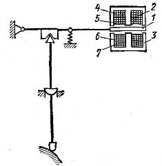
The principle of operation of the simplest electrocopiers is shown in fig. 1. In this diagram, the workpiece 1 is processed by the spindle 3 with the finger mill 2, the milling device 4 is connected to the copy head by a rigid connection 5. …
The pin supports and guides are such that lateral pressure on the copy pin is converted into axial displacements of the copy head pin.The template 9 is located on the table 10, on which the workpiece is also mounted. Drive 11 continuously moves the table in the direction indicated by the arrow. This feed is called the lead or main feed.
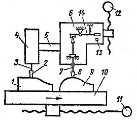
Rice. 1. Electric milling cutter
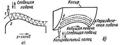
Rice. 2. Trajectories of the tracking finger
Another device 12 moves the copying and milling heads in a vertical direction. This feed is called tracking. The control is constructed in such a way that when the contact 13 is open, the device 12 moves the copying finger closer to the template. When contact 13 is closed, device 12 moves the tracking finger away from the template. When the contact 13 is open, the movement of the copying finger 8 starts forward towards the template 9.
When it comes into contact with the pattern, the finger 8 of the copying head is pulled back, the lever 14 is rotated and the contact 13 is closed. The copy head starts to move backwards. The copying finger 8 is removed from the template 9 and contact 13 is opened. Then the copying finger will again approach the template and due to the continuity of the guide channel, the template will shift and the copying finger will touch the template at a different point.
As a result of periodic advances and retreats of the copying finger with a continuous leading feed, the copying finger describes its saw trajectory, wrapping it around the template (Fig. 2, a). The same trajectory is described with respect to the workpiece by a rotating knife 2 firmly connected to the copying head 6 (see Fig. 1).
At the end of the longitudinal feed stroke, the cross feed is activated automatically. The cutter and copying finger are moved in a direction perpendicular to the plane of the drawing (Fig. 2, b).The lead feed is reversed and the tracker pin and cutter begin to move in the opposite direction. In this case, the finger moves along the new form of the volume pattern and the cutter makes a new move along the curved surface of the part. The part is processed in several passes. Roughing is done first. After that, finishing is done according to the same pattern. The irregularities are then smoothed out with an abrasive tool.
A similar method can be used to machine bodies of rotation with curvilinear generators or step shapes on electrocopying lathes. Copies of such machines have only two feeds: leading (longitudinal) and tracking (transverse). During the copying process, only one of the two mutually perpendicular channels is changed. Such copying is called uniaxial copying. In uniaxial copying, shoulder processing parallel to the next feed direction is not possible.
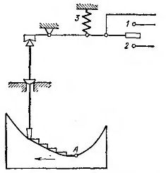
Rice. 3. Three-position copy head
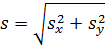
Rice. 4. Inductive copy head
Using a two-contact copy head (Fig. 3), called three-position, also allows you to control the lead feed, including when both contacts of the copy head are open. When the copying finger of such a head does not come into contact with the surface of the template, contact 1 closes under the action of spring 3. In this case, the finger moves to the template, and the cutter moves to the part. Lead submission is disabled. When a finger is pressed against the pattern, contact 1 opens, forward movement of the finger is stopped and lead feeding begins. In this case, the tip of the copying finger moves away from the template, contact 1 closes again and a new movement of the copying finger towards the template begins.
This alternating movement of the fingers to the pattern and to the right will continue to point A, the inflection point of the pattern curve. At this moment, the longitudinal feed due to the change in the direction of the inclination of the profile leads to an increase in the pressure on the copying finger and the closing of contact 2. In this case, the control system will ensure the retraction of the copying head and the finger will move away from the template. Contact 2 will open and the longitudinal feed will turn on again, etc. Thus, with a three-position copy head, the contour is bypassed by alternating longitudinal and transverse movements. Copying using a three-position head, where the feed is controlled in both coordinates, is called two-coordinate.
The speed of rotation of the electric motors of the systems under consideration does not change during the copying process. The amount of feed is set by changing the kinematic chains.
Copy heads connected to a low voltage circuit (usually 12 V). This is due to both the small distance between the contacts and the desire to reduce the destruction of the contacts due to sparking. The sensitivity of the copy head and the size of the gap between the contacts are determined by the lever system used and the inertia of the feeder.
Another stage in the development of electrocopying was inductive copying heads... In such a head (Fig. 4) each position of the copying finger corresponds to the position of the armature 1 placed between the cores 2 and 3. Coils 4-7 are placed on the middle rods of these cores . Each core with two windings forms a transformer. The whole system is called a differential transformer.
Primary windings 4 and 7 are connected in series and are included in the alternating current network; secondary windings 5 and 6 are connected to each other so e. etc. v. directed in opposite directions. When anchor 1 is in the middle position, e.g. etc. c. the secondary windings are balanced. Approaching the armature to one of the cores leads to the fact that the magnetic flux in it increases, while in the other core it decreases. The resulting difference in e. etc. c. secondary windings are used for stepless control of variable feed drives.
Two-position and three-position copy heads typically operate with electromagnetic clutches that engage, disengage, and reverse all feeds. A simplified schematic diagram of a copier with a three-position head is shown in Fig. 5.When the copying finger does not touch the template, contact 1 closes. In this case, the relay of the tracking power supply 1PC and the coil of RVP1 of the leading power supply turn on. When the electromagnetic clutch MB is on, it is fed forward (toward the pattern). The RVP relay has two coils RVP1 and RVP2 and is activated when one of them is switched on. In this case, the coil of RVP1 is turned on and the contact of RVP is open.
When the tracer finger presses the surface of the tracer, contact 1 will open and feed forward will stop. In addition, the RVP1 coil is turned off, the RVP opening contact is closed, the ML connector is turned on, and the left power supply starts (when the MP connector is turned on, the right power supply starts). The copying finger moves in this case.
If the pressure on the copy finger is reduced, the contact will close again and the copy finger will move into the pattern.If the profile of the pattern is such that the displacement causes the pressure on the copying finger to increase, then contact 2 closes, another relay 2PC of the tracking power and RVP2 of the coil of the RVP relay turn on. This will engage the MH clutch and begin to move the copy finger away from the pattern. If the P switch is moved to the up position, instead of feeding to the left, a longitudinal feed to the right will result.
Electrical contact copier heads and electromagnetic clutches used in universal machine copiers. Copying errors are usually in the range of 0.05-0.1mm. Home machines specially designed for electrocopying have inductive copy heads and feeders whose speed is controlled automatically.
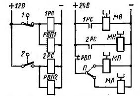
Rice. 5. Schematic of an electrocopying lathe
Rice. 6. Power supplies for electrocopying
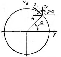
When using variable feed drives, in order to ensure accurate copying, high productivity and surface cleanliness, it is necessary that the tangent of the feed to the contour is constant in size and does not depend on the angle of inclination of the profile. Let the contour to be copied be a circle (Fig. 6):
where sx and sy are leading and trailing emissions, mm/min, respectively.
If the resulting feed rate vector is tangent to the contour, then


Thus, for the highest accuracy and productivity, the feed rates must be variable and interconnected.
Control copying from non-contact copy heads is performed in the function of moving the copy finger relative to its neutral position.Since when there is no offset, the tracking pin and the cutter are in the same positions, the control in the finger offset function is control according to the discrepancy between the positions of the finger and the cutter (proportional control).
In order to improve the processing quality, in addition to the control by the misalignment, control by the rate of change of the misalignment (from the derivative of the displacement with respect to time) is introduced. With this differential control, the system reacts more quickly to any change in the slope of the copier profile and the processing accuracy is increased.
In addition to control in the discrepancy function and in its derivative function, control is also used in the function of the integral of the discrepancy in time (integral control). In this case, not only the size of the discrepancy is taken into account, but also the time during which it occurred. In this case, the system acquires the property, in the absence of additional commands, to move in the same direction as in the previous section of the road. This movement is similar to taking off. The integral control allows, in the case of a constant slope of the profile, to carry out stepless copying with a constant position of the copying finger. In case of sharp changes in the outline of the template, the action of the integral control is neutralized by the action of the differential control.
In combined control, the sum of three voltages is fed to a special electronic unit proportional to the value of the mismatch, its derivative and the time integral, respectively, and the power drives are controlled as a function of all these three values.In this case, processing errors can be reduced.
In the industry of metal cutting machines, various hydrocopiers are installed on universal and specialized machines. Both fixed and variable feed devices are used, and the hydraulic drive makes it possible to simply provide infinitely variable feed control over a wide range.
Hydrocopying systems are fast. They can provide uniaxial and biaxial copying. Hydrocopier systems successfully compete with electric ones in processing accuracy. A large number of electrocopiers and hydrocopiers are now in operation in local engineering plants. Electric copying allows you to perform processing and according to the drawing placed in the machine, which is used instead of a copier.