Electromagnetic couplings
 In principle, the electromagnetic clutch resembles an asynchronous motor, at the same time it differs from it in that the magnetic flux in it will be created not by a three-phase system, but by rotating poles excited by direct current.
Electromagnetic clutches are used to close and open kinematic circuits without stopping rotation, for example in gearboxes and gearboxes, as well as to start, reverse and brake machine tool drives. The use of clutches allows you to separate the start of motors and mechanisms, reduce the time of starting the current, eliminate shocks in both electric motors and mechanical transmissions, ensure smooth acceleration, eliminate overloads, slippage, etc. A sharp reduction in starting losses in engines removes the limit on the allowable number of starts, which is very important in the cyclic operation of the engine.
The electromagnetic clutch is an individual speed regulator and is an electrical machine used to transmit torque from the drive shaft to the driven shaft using an electromagnetic field and consists of two main rotating parts: an armature (in most cases this is a massive body) and field wound inductor ... The armature and the inductor are not mechanically rigidly connected to each other. Usually the armature is connected to the driving motor and the inductor is connected to the running machine.
When the drive motor of the clutch drive shaft rotates, in the absence of current in the excitation coil, the inductor, and with it the driven shaft, remain stationary. When direct current is applied to the excitation coil, a magnetic flux occurs in the magnetic circuit of the coupling (inductor - air gap - armature). When the armature rotates relative to the inductor, an EMF is induced in the former and a current arises, the interaction of which with the magnetic field of the air gap causes the appearance of an electromagnetic torque.
Electromagnetic induction couplings can be classified according to the following criteria:
-
based on the torque principle (asynchronous and synchronous);
-
by the nature of the distribution of magnetic induction in the air gap;
-
by the construction of the armature (with massive armature and with armature with squirrel-cage type winding);
-
by the method of supplying the excitation coil; by way of cooling.
Armored and inductor connectors are the most widely used due to the simplicity of their design.Such couplings mainly consist of a toothed field-wound inductor mounted on one shaft with conductive slip rings and a smooth cylindrical solid ferromagnetic armature connected to the other shaft of the coupling.
Device, principle of operation and characteristics of electromagnetic couplings.
Electromagnetic clutches used for automatic control are divided into dry and viscous clutches and sliding clutches.
A dry friction clutch transmits power from one shaft to another through friction discs 3. The discs have the ability to move along the splines of the shaft axis and the driven half-coupling. When current is applied to coil 1, armature 2 compresses the discs between which there is a frictional force. The relative mechanical characteristics of the clutch are shown in Fig. 1, b.
Viscous friction clutches have a constant clearance δ between the master 1 and slave 2 half clutches. In the gap, with the help of coil 3, a magnetic field is created, which acts on the filler (ferrite iron with talc or graphite) and forms elementary chains of magnets. In this case, the filler seems to catch the driven and driven half-couplings. When the current is switched off, the magnetic field disappears, the circuits are broken and the semi-connectors slide relative to each other. The relative mechanical characteristics of the clutch are shown in Fig. 1, e. These electromagnetic clutches allow smooth control of the rotation speed under high loads on the output shaft.
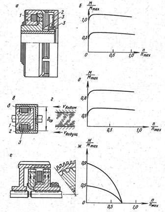
Electromagnetic couplings: a — diagram of dry friction coupling, b — mechanical characteristic of friction coupling, c — diagram of viscous friction coupling, d — diagram of engagement of ferrite filler, e — mechanical characteristic of viscous friction coupling, e — diagram of a sliding clutch, g — mechanical slip clutch.
A sliding clutch consists of two semi-couplers in the form of teeth (see Fig. 1, e) and a coil. When current is applied to the coil, a closed magnetic field is formed. When rotating, the connectors slide relative to each other, as a result of which an alternating magnetic flux is formed, this is the reason for the occurrence of EMF. etc. v. and currents. The interaction of the generated magnetic fluxes drives the driven half-link in rotation.
The characteristic of the clutch friction half is shown in fig. 1, g. The main purpose of such clutches is to create the most favorable starting conditions, as well as to smooth out dynamic loads during engine operation.
Electromagnetic sliding clutches have a number of disadvantages: low efficiency at low revolutions, low transmitted torque, low reliability in case of sudden changes in load and significant inertia.
The figure below shows a schematic diagram of the slip clutch control in the presence of speed feedback using a tachogenerator connected to the output shaft of the electric drive. The signal from the tachogenerator is compared with the reference signal and the difference of these signals is fed to the amplifier Y, from the output of which the excitation coil of the OF coupling is fed.
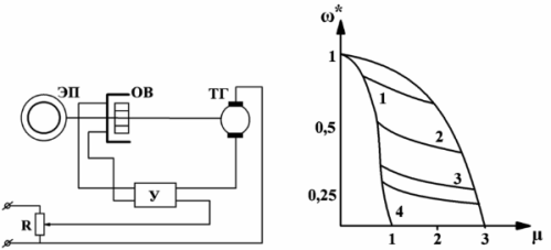
NBasic control scheme sliding clutches and artificial mechanical characteristics with automatic adjustment
These characteristics are located between curves 5 and 6, which correspond practically to the minimum and nominal values of the coupling excitation currents. Increasing the drive speed control range is associated with significant losses in the slip clutch, which mainly consist of losses in the armature and in the field winding. In addition, armature losses, especially with increasing slip, significantly prevail over other losses and amount to 96 — 97% of the maximum power transmitted by the coupling. At a constant load moment, the speed of rotation of the clutch drive shaft is constant, i.e. n = const, ω = const.
I have electromagnetic powder couplings, the connection between the driving and driven parts is carried out by increasing the viscosity of the mixtures filling the gap between the coupling surfaces of the couplings with an increase in the magnetic flux in this gap. The main component of such mixtures are ferromagnetic powders, for example, carbonyl iron. In order to eliminate the mechanical destruction of iron particles due to frictional forces or their adhesion, special fillers are added - liquid (synthetic fluids, industrial oil or bulk (zinc or magnesium oxides, quartz powder). Such connectors have a high reaction speed, but their operational reliability is insufficient for wide application in mechanical engineering.
Let's look at one of the schemes for smoothly adjusting the rotation speed from the ID drive, which works through the sliding clutch M to the MI drive.
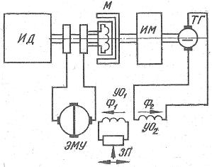
Scheme of inclusion of the sliding clutch for adjusting the speed of rotation of the drive
When the load on the drive shaft changes, the output voltage of the TG tachogenerator will also change, as a result of which the difference between the magnetic fluxes F1 and F2 of the electric machine amplifier will increase or decrease, thus changing the voltage at output of the EMU and the magnitude of the current in the clutch coil.
Electromagnetic couplings ETM
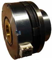
Electromagnetic clutches of the ETM series with magnetically conductive discs are of contact (ETM2), non-contact (ETM4) and brake (ETM6) designs. Couplings with a current wire on a contact are distinguished by low reliability due to the presence of a sliding contact, therefore, in the best drives electromagnetic couplings with a fixed wire are used. They have additional air gaps.
Contactless couplings are distinguished by the presence of a composite magnetic circuit formed by a spool body and seat, which are separated by so-called ballast clearances. The spool seat is fixed while the contact current wire elements are disconnected. Due to the clearance, the transfer of heat from the friction discs to the coil is reduced, which increases the reliability of the clutch under severe conditions.
It is recommended to use ETM4 couplings as guides, if permitted by the installation conditions, and ETM6 couplings as brake couplings.
ETM4 clutches operate reliably at high speed and frequent starts. These clutches are less sensitive to oil contamination than ETM2, the presence of solid particles in the oil can cause abrasive wear of the brushes, therefore ETM2 clutches can be used if there are no certain restrictions and the installation of ETM4 clutches is difficult according to installation design conditions.
Couplings with ETM6 design are to be used as brake couplings. Connectors ETM2 and ETM4 must not be used for braking according to the "inverted" scheme, i.e. with rotating clutch and fixed strap. To select couplings, it is necessary to evaluate: static (transmitted) torque, dynamic torque, transient time in the drive, average losses, unit energy and residual torque at rest.