Stator and rotor windings of alternating current electrical machines
Winding of an electrical product (device) — a set of coils or coils located in a certain way and connected, designed to create or use a magnetic field, or to obtain a given value of resistance of an electrical product (device). Winding coil of an electrical product (device) — a coil of an electrical product (device) or part of it, made as a separate structural unit (GOST 18311-80).
The article tells about the device of the stator and rotor windings of electric machines with alternating current.
Spatial arrangement of the stator windings:
 Squirrel cage rotor:
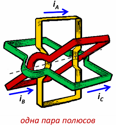
A stator with twelve slots, in each of which one wire is laid, is schematically shown in fig. 1, a. The connections between the stranded wires are indicated for only one of the three phases; the beginning of phases A, B, C of the coil are marked C1, C2, C3; ends — C4, C5, C6.The parts of the coil laid in the channels (the active part of the coil) are conventionally shown in the form of rods, and the connections between the wires in the grooves (end connections) are shown as a solid line.
The stator core has the shape of a hollow cylinder, which is a stack or a series of stacks (separated by ventilation ducts) made of sheets of electrical steel. On small and medium-sized machines, each sheet is stamped in the form of a ring with grooves along the inner circumference. In fig. 1, b, a stator sheet with grooves of one of the forms used is given.
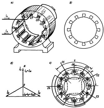
Rice. 1. The location of the winding in the slots of the stator and the distribution of currents in the wires
Let the instantaneous value of the current iA of the first phase at a certain point in time be maximum and the current is directed from the beginning of the phase C1 to its end C4. We will consider this current to be positive.
Determining the instantaneous currents in the phases as a projection of the rotating vectors on the fixed axis ON (Fig. 1, c), we get that the currents of phases B and C at a given moment are negative, that is, they are directed from the ends of the phases to the beginning.
Let us trace it in fig. 1d the formation of a rotating magnetic field. At the moment in question, the current of phase A is directed from its beginning to the end, that is, if in wires 1 and 7 it leaves us outside the plane of the drawing, then in wires 4 and 10 it goes behind the plane of the drawing to us (see Fig. 1, a and d).
In phase B, the current at this point in time passes from the end of the phase to its beginning.By connecting the wires of the second phase according to the sample of the first, it can be obtained that the current of phase B passes through wires 12, 9, 6, 3; at the same time, through wires 12 and 6, the current leaves us outside the plane of the drawing, and through wires 9 and 3 - to us. We obtain a picture of the distribution of currents in phase C using the sample from phase B.
The directions of the currents are given in fig. 1, d; dashed lines show the magnetic field lines generated by the stator currents; the directions of the lines are determined by the right-hand screw rule. It can be seen from the figure that the wires form four groups with the same current directions and the number of 2p poles of the magnetic system is four. The regions of the stator where the magnetic lines leave the stator are the north poles and the regions where the magnetic lines enter the stator are the south poles. An arc of a stator circle occupied by one pole is called pole separation.
The magnetic field at different points on the stator circumference is different. The pattern of magnetic field distribution along the stator circumference is repeated periodically through each two-pole separation. Arc angle 2 taken as 360 electrical degrees. Since there are p double pole divisions around the circumference of the stator, 360 geometric degrees equal 360p electrical degrees, and one geometric degree equals p electrical degrees.
In fig. 1d shows the magnetic lines for a certain fixed moment in time. If we look at the picture of the magnetic field for several consecutive moments in time, we can make sure that the field rotates at a constant speed.
Let's find the rotational speed of the field.After a time equal to half the period of the alternating current, the directions of all the currents are reversed, due to which the magnetic poles are reversed, that is, in half the period the magnetic field rotates by a fraction of a revolution. The rotational speed of the stator magnetic field, i.e. the synchronous speed, is (in revolutions per minute)

The number p of pole pairs can only be an integer, therefore at a frequency of, for example, 50 Hz, the synchronous speed can be equal to 3000; 1500; 1000 rpm etc.
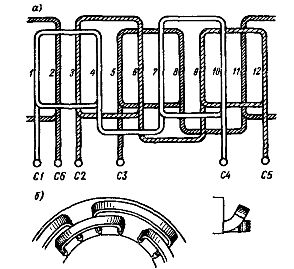
Rice. 2. Detailed diagram of a three-phase single-layer winding
The windings of an alternating current machine can be divided into three groups:
1) reel to reel;
2) core;
3) special;
Special coils include:
(a) short circuit in the form of a squirrel cage;
b) winding of an asynchronous motor with switching to a different number of poles;
c) winding of an asynchronous motor with anti-connections, etc.
In addition to the above division, coils differ in a number of other characteristics, namely:
1) by the nature of execution — manual, patterned and semi-patterned;
2) by location in the groove - single-layer and two-layer;
3) by the number of slots per pole and phase — windings with an integer q slots per pole and phase and windings with a fractional number q.
A coil is a circuit formed by two wires connected in series. A section or winding is a series of turns connected in series, located in two slots and with common insulation from the body.
The section has two active sides. The left active side is called the start of the section (coil) and the right side is called the end of the section. The distance between the active sides of the section is called the section pitch. It can be measured either by the number of prongs or in parts of the pole divisions.
The pitch of the section is called diametral if it is equal to the pole division and truncated if it is less than the pole division, since the section pitch is not greater than the pole division.
A characteristic quantity that determines the operation of the coil is the number of slots per pole and phase, i.e. the number of slots occupied by the winding of each phase within one pole division:

where z is the number of stator slots.
The coil shown in fig. 1, a, has the following data:

Even for this simplest coil, the spatial drawing of the wires and their connections turns out to be complicated, so it is usually replaced by an expanded diagram, where the winding wires are depicted not on a cylindrical surface, but on a plane (a cylindrical surface with grooves and a coil "unfolds » in a plane). In fig. 2 is a detailed diagram of the considered stator winding.
In the previous figure, for simplicity, it was shown that part of the phase A of the winding placed in slots 1 and 4 consists of only two wires, that is, one turn. In fact, each such part of the winding falling on one pole consists of w turns, that is, in each pair of grooves w wires are placed, combined into one winding. Therefore, when bypassing according to the extended scheme, for example, phase A of slot 1, it is necessary to bypass slots 1 and 4 w times before moving to slot 7. The distance between the sides of the turn of one winding or winding step, y is shown in fig. 1, d; usually expressed in terms of the number of channels.
Rice. 3. Asynchronous machine shield
Shown in fig.1 and 2, the stator winding is called single-layer, since it fits into each groove in one layer. To place the intersecting front parts in a plane, they are bent on different surfaces (Fig. 2, b). Single-layer windings are made with a step equal to the separation of the poles (Fig. 2, a), or this step is equal on average to the separation of the poles for different windings of the same phase, if y> 1, y< 1... In our days double layer coils are more common.
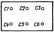
The beginning and end of each of the three phases of the winding is indicated on the machine panel, where there are six clamps (Fig. 3). Three linear wires of a three-phase network are connected to the upper terminals C1, C2, SZ (the beginning of the phases). The lower clamps C4, C5, C6 (the ends of the phases) are either connected to one point with two horizontal jumpers, or each of these clamps is connected to a vertical jumper with the upper clamp lying above it.
In the first case, the three phases of the stator form a star connection, in the second - a delta connection. If, for example, one phase of the stator is designed for a voltage of 220 V, then the line voltage of the network to which the motor is connected must be 220 V, if the stator is connected with a delta; when connected with a star, the grid line voltage should be
When the stator is connected in star, the neutral wire is not energized because the motor is a symmetrical load to the network.
The rotor of an induction machine is made of stamped sheets of insulated electrical steel on a shaft or on a special supporting structure. The radial clearance between the stator and the rotor is as small as possible to ensure low resistance in the path of the magnetic flux penetrating both parts of the machine.
The smallest gap allowed by the technological requirements is from a tenth of a millimeter to several millimeters, depending on the power and dimensions of the machine. The conductors of the rotor winding are located in the slots along the rotor forming directly on its surface to ensure the greatest contact of the rotor winding with the rotating field.
Induction machines are manufactured with both phase and squirrel-cage rotors.

Rice. 4. Phase rotor
A phase rotor usually has a three-phase winding, made like a stator winding, with the same number of poles. The winding is connected in star or delta; the three ends of the coil are led to three insulated slip rings which rotate with the machine shaft. Through brushes mounted on the stationary part of the machine and sliding on slip rings, a three-phase starting or regulating rheostat is connected to the rotor, i.e., an active resistance is introduced into each phase of the rotor. The external view of the phase rotor is shown in fig. 4, three slip rings are visible at the left end of the shaft. Asynchronous motors with a wound rotor are used where smooth regulation of the speed of the drive mechanism is required, as well as in frequent starts of the motor under load.
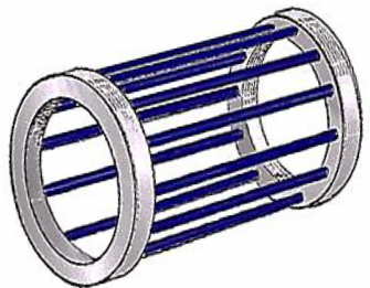
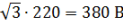
The design of a squirrel cage rotor is much simpler than that of a phase rotor. For one of the designs in FIG. 5a shows the shape of the sheets from which the rotor core is assembled. In this case, holes near the outer circumference of each sheet form longitudinal channels in the core. Aluminum is poured into these channels, after its solidification, longitudinal conductive rods are formed in the rotor.At both ends of the rotor, aluminum rings are simultaneously cast, which short-circuit the aluminum rods. The resulting conductive system is commonly called a squirrel cage.
Rice. 5. Squirrel cell rotor
A cage rotor is shown in fig. 5 B. At the ends of the rotor, ventilation blades can be seen cast simultaneously with short-coupling rings. In this case, the slots are beveled by one division along the rotor. The squirrel cage is simple, there are no sliding contacts, therefore three-phase asynchronous squirrel cage motors are the cheapest, simplest and most reliable; they are the most common.