Devices for built-in temperature protection of UVTZ-1 and UVTZ-4A electric motors
 A combination of fuses with magnetic starters as well as circuit breakers is used to protect electric motors from short circuits and overloads. The lack in some cases of the technical possibility to permanently adjust the thermal protection sets new requirements for the development of built-in temperature protection.
As practice shows, the built-in temperature protection effectively shuts down electric motors in case of prolonged overloads, incorrect start and stop processes, increased switching frequency, phase failure, fluctuations in the mains voltage within 70 ... 110% of the nominal value, silencing of an actuator, including the electric motor with a stuck rotor. Increased ambient temperature, irregularities in the cooling system.
The temperature protection consists of temperature sensors and a control device.
The temperature sensors are semiconductor thermistors — posistors or resistors built into the front part of the stator winding (one in each phase).
Characteristic property posistor — high sensitivity in a narrow temperature range. For example, an industrial CT5-1 posistor, which can be used in a built-in motor temperature protection circuit, has an almost constant resistance in the temperature range from 60 to 100 °, and in the range from 120 to 130 °, its resistance increases several thousand times .
Cobalt-manganese thermistors of the TR-33 type, operating in relay mode, are used as temperature sensors for built-in protection devices. There are six options for TP-33 thermo-freezing working groups, each of which corresponds to a minimum and maximum working temperature within 5 °.
The built-in protection with thermal resistances ТР-33 is adjusted depending on the insulation class of the protected electric motor. Adjustment is done either by varying the voltage applied to the thermistor. or shunts with additional resistance with thermal resistance.
The largest practical application for sensors for built-in temperature protection of electric motors is positive output thermistors temperature coefficient of resistance CT14-1A (t ° av.-130 °) or ST 14-1 B (t ° av.-105 °).
CT14-1A thermistors are produced in the form of disks with a diameter of 3 and a thickness of 1.5 mm. A set of such sensors (three discs per phase) is a sensitive protective element that sends a signal to the control unit.
Currently, two types of devices with built-in temperature protection are produced - UVTZ-1 and UVTZ-4A. Their principle of operation is the same, although the scheme and design are different.
Temperature protection devices are unified for all standard sizes of electric motors, are interchangeable and do not require adjustment and adjustment during installation and operation.
The control device serves to amplify the signal coming from the temperature sensors built into the stator winding of the electric motor and convert it into a signal that controls the shutdown magnetic starters (such as PML, PME, etc.).
The UVTZ-1 device consists of a converter and an output relay. The RZS-6 is used as an output relay, which gives a signal to control a magnetic starter.
The circuit automatically monitors its operation, that is, guarantees the shutdown of the electric motor in the event of a malfunction in any element of temperature protection. If the temperature sensors are damaged or the chain of their connection with the control device is broken, the latter does not allow the electric motor to be connected to the network.
In the event of a short circuit, at the cost of sensors with a control device, the transistors will close, the control transition of the transistor is vented, the relay turns off and, with its contacts, cuts off the power supply to the magnetic stub starter coil.
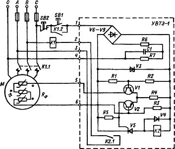
Rice. 1. Electrical schematic diagram of the built-in temperature protection of UVTZ-1 electric motors
Temperature sensors are installed in asynchronous motors in the factory during their manufacture or overhaul, as well as in working electric motors during operation. After their installation, the resistance of the entire sensor circuit is measured, which at a temperature of 20 ± 5 ° should be within 120 ... 150 Ohm.
The measuring current of the applied ohmmeter cannot exceed 50 mA.and the voltage is 2.5 V. Megohmmeters are not allowed for these purposes.
Measure the insulation resistance of the sensors to the motor winding and housing with a 500 V megger, the value of this resistance should not exceed 0.5 MΩ.
The device is designed to operate in an upright position, can be mounted on walls and structures that are not subject to shock or strong vibration, and should not be exposed to constant heat, including sunlight. It can be housed in control stations, prefabricated switchgear and individual cabinets.
The control device is connected to the sensor with an insulated wire with a cross section of at least 0.5 mm2 for copper wires and 1.0 mm2 for aluminum wires.
The operability of the installed device is checked by pressing the "Start" button on the magnetic starter. If the electric motor is in good condition and the sensors of the device and the magnetic starter are correctly connected, and if they are in good condition, the electric motor rotates.
After making sure it idles normally, you need to open the sensor circuit in the engine terminal box. If at the same time the electric motor is disconnected from the network, it means that the built-in protection device is working normally. Recheck the protection by shorting the sensor circuit in the terminal box. In this case, the electric motor must also be disconnected from the mains.