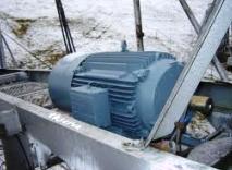
Frequency converter for electric motor
Technical aspects of using frequency converters
 Nowadays, the induction motor has become the main device in most electric drives. Increasingly, a frequency converter is used for control - an inverter with PWM regulation. Such control gives many advantages, but also creates some problems when choosing certain technical solutions. Let's try to understand them in more detail.
The device of frequency converters
The development and production of a wide range of powerful high-voltage transistor IGBT modules made it possible to implement multiphase power switches controlled directly by digital signals. Programmable computing facilities made it possible to generate numerical sequences at the switch inputs that provided signals frequency control of asynchronous electric motors… The development and mass production of single-chip microcontrollers with large computing resources made possible the transition to servo drives with digital controllers.
Power frequency converters, as a rule, are implemented according to a scheme containing a rectifier based on powerful diodes or power transistors and an inverter (controlled switch) based on IGBT transistors shunted by diodes (Fig. 1).
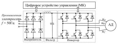
Rice. 1. Frequency converter circuit
The input stage rectifies the supplied sinusoidal grid voltage, which, after smoothing with an inductive-capacitive filter, serves as a power source for the controlled inverter, which generates a signal with pulse modulation, which generates sinusoidal currents in the stator windings with parameters that provide the necessary operating mode of the electric motor.
Digital control of the power converter is carried out using microprocessor hardware and software corresponding to the tasks at hand. The computing unit generates control signals for 52 modules in real time and also processes signals from measurement systems that control the operation of the drive.
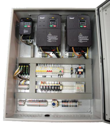
Power supplies and control computers are combined in a structurally designed industrial product called a frequency converter.
There are two main types of frequency converters used in industrial equipment:
-
proprietary converters for specific types of equipment.
-
universal frequency converters are designed for multifunctional control of AM operation in user-defined modes.
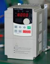
Setting and managing the operating modes of the frequency converter can be done using the control panel equipped with a screen to indicate the entered information.For simple scalar frequency control, you can use a set of simple logic functions available in the controller's factory settings and the built-in PID controller.
To implement more complex control modes using feedback sensor signals, it is necessary to develop an ACS structure and an algorithm to be programmed using a connected external computer.
Most manufacturers produce a range of frequency converters that differ in input and output electrical characteristics, power, design and other parameters. Additional external elements can be used to connect to external equipment (mains, motor): magnetic starters, transformers, chokes.
Types of control signals
It is necessary to distinguish between the different types of signals and use a separate cable for each. Different types of signals can influence each other. In practice, this separation is common, for example a cable from pressure sensor can be connected directly to the frequency converter.
In fig. 2 shows the recommended way to connect the frequency converter in the presence of various circuits and control signals.
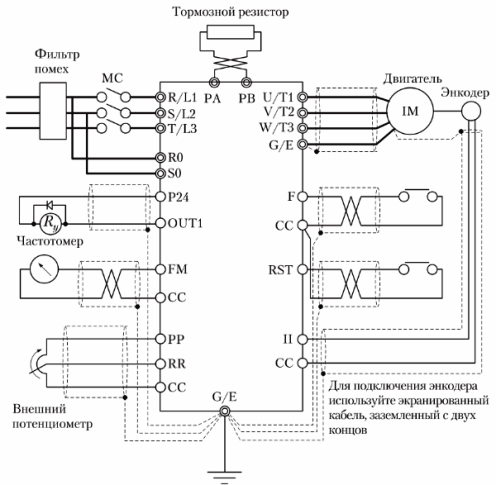
Rice. 2. An example of connecting the power circuits and the control circuits of the frequency converter
The following types of signals can be distinguished:
-
analog - voltage or current signals (0 … 10 V, 0/4 … 20 mA), the value of which changes slowly or rarely, usually these are control or measurement signals;
-
discrete voltage or current signals (0 … 10 V, 0/4 … 20 mA), which can take only two rarely changing values (high or low);
-
digital (data) — voltage signals (0 … 5 V, 0 … 10 V) that change quickly and with a high frequency, usually these are signals from ports RS232, RS485, etc.;
-
relay — relay contacts (0 … 220 V AC) may include inductive currents depending on the connected load (external relays, lamps, valves, brakes, etc.).
Frequency converter power selection
Real devices have many aspects that can cause the current load on the device to increase, for example during startup. In principle, using a frequency drive allows you to reduce current and mechanical loads due to the soft start. For example, the starting current is reduced from 600% to 100-150% of the rated current.
Drive at a reduced speed
It should be remembered that although the frequency converter easily provides 10: 1 speed regulation when the motor is running at low speeds, the power of its own fan may not be sufficient. Monitor engine temperature and provide forced ventilation.
Electromagnetic compatibility
It is powered by an emergency generator
The soft start that is provided by the frequency converter allows to reduce the required power of the generator. Since with such a start the current decreases by 4-6 times, then the power of the generator can be reduced by a similar number of times. But a contactor must still be installed between the generator and the drive, controlled by the relay output of the frequency drive. This protects the frequency converter from dangerous overvoltages.
Supplying a three-phase converter from a single-phase network
Three-phase frequency converters can be powered from a single-phase network, but their output current must not exceed 50% of the rated one.
Save energy and money
Savings come from several reasons. First, because of growth cosine phi to values of 0.98, i.e. the maximum power is used to do useful work, the minimum is wasted. Second, a coefficient close to this is obtained in all engine operating modes.
Without a frequency converter, asynchronous motors at low load have a cosine phi of 0.3-0.4. Third, there is no need for additional mechanical adjustments (dampers, throttles, valves, brakes, etc.), everything is done electronically. With such a control device, the savings can be up to 50%.
Sync multiple devices
Network protection against higher harmonics
For additional protection, in addition to short shielded cables, line chokes and bypass capacitors are used. Throttlein addition, it limits the inrush current when switched on.
Choosing the right protection class
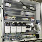
Reliable heat dissipation is essential for the smooth operation of the frequency drive. If high protection classes are used, for example IP 54 and higher, it is difficult or expensive to achieve such heat dissipation. Therefore, it is possible to use a separate cabinet with a high degree of protection, where modules of a lower class can be installed and general ventilation and cooling can be carried out.
Parallel connection of electric motors to one frequency converter
To reduce costs, one frequency converter can be used to control several electric motors. Its power should be selected with a margin of 10-15% of the total power of all electric motors. In doing so, it is necessary to minimize the length of the motor cables and it is highly desirable to install a motor choke.
Most frequency converters do not allow motors to be switched off or connected via contactors while the frequency drive is running. This is done only through the stop command on the device.
Control function setting
 In order to achieve the maximum performance of the electric drive, such as: power factor, efficiency, overload capacity, regulation smoothness, durability, it is necessary to correctly choose the ratio between the change in the operating frequency and the output voltage of the frequency converter.
The voltage change function depends on the torque character of the load. At constant torque, the motor stator voltage must be controlled in proportion to the frequency (scalar control U / F = const). For a fan, for example, another ratio is U / F * F = const. If we increase the frequency by 2 times, then the voltage should increase by 4 (vector control). There are devices with more complex control functions.
Advantages of using a variable speed drive with a frequency converter
In addition to increasing efficiency and saving energy, such an electric drive allows you to get new driving qualities. This is reflected in the rejection of additional mechanical devices that create losses and reduce the reliability of systems: brakes, shock absorbers, throttles, valves, control valves, etc. Braking, for example, can be done by reversing the electromagnetic field in the motor's stator. By changing only the functional relationship between frequency and voltage, we get a different drive without changing anything in the mechanics.
Reading the documentation
It should be noted that although the frequency converters are similar to each other, and having mastered one, it is easy to deal with the other, however, it is necessary to carefully read the documentation. Some manufacturers impose restrictions on the use of their products and if these are violated, they remove the product from the warranty.
You may be interested in: Variable electric drive as a means of saving energy