RT40 series current relay
 PT40 overcurrent relays are designed for use in relay protection and automation circuits. These relays respond to an increase in current in the monitored circuit and are indirect relays. The construction of the PT40 overcurrent relay is shown in fig. 1.
The relay consists of the following main elements: a U-shaped steel core 1 with mounted current coils 2, a movable system consisting of an armature 3, a movable contact 5 and a shock absorber 22, an aluminum stand 23, stops left 6 and right (in Fig. 2.4 , but not shown), an insulating block 9 with two pairs of fixed contacts located on it (Fig. 1, b) 7 and 8, an adjusting block (Fig. 1, c), consisting of a spring holder 10, a shaped screw 11 with a split hexagonal sleeve 12 mounted on it, against a spiral spring 14 and a spring washer 18, an adjustment scale 13 and an adjustment indicator 14, a contact assembly (Fig. 1, d) , consisting of a fixed spring contact 19, in one of the ends of which has a silver band, a front stop 20 and a rear flexible stop 21.
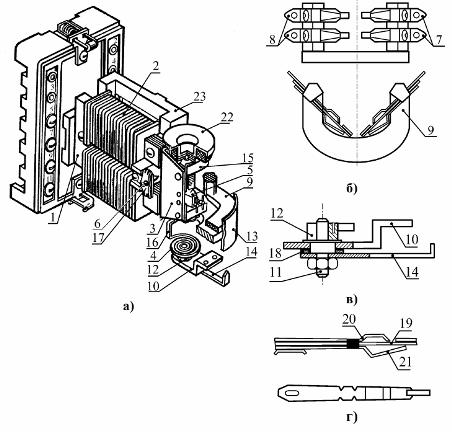
Rice. 1.Electromagnetic relay with maximum current of the RT40 series: a — relay construction, b — insulating block with fixed contacts, c — regulating block, d — contact device.
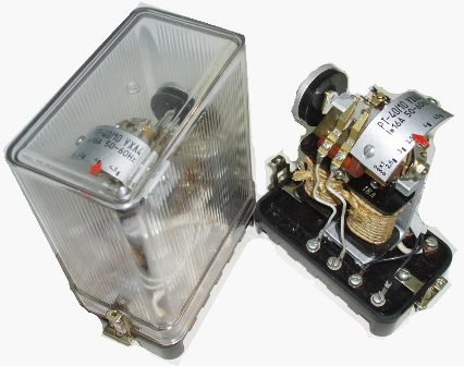
The PT40 current relay is mounted in a housing consisting of a plastic base and a transparent material housing. To reduce losses in the steel due to eddy currents, the core is assembled from electrical steel plates insulated from each other.
When the electromagnetic force of the relay exceeds the mechanical force of the spring, the armature is attracted to the electromagnet. In this case, the movable contact bridge closes one pair of fixed contacts and opens the second pair.
The relay is designed for installation in a vertical plane, deviation from the vertical position due to the imbalance of the moving relay system leads to an additional error.
A vibration damper 22 (vibration damper) in the form of a toroid filled with quartz sand is connected to the axis of the armature. With each acceleration of the anchor and its associated moving system, some of the kinetic energy is expended in overcoming the frictional forces between grains of sand. With the help of a vibration damper, the vibrations of both the entire moving system and the contacts when they are switched on are reduced.
The operating current is adjusted by changing the preload of the spiral spring 4, which is attached to the armature using the tail 16. The preload of the spring is fixed by the arrow 14.
The coil of relay 2 is divided into two sections, which can be connected in series or parallel if necessary.
The pickup setting of the PT40 series relay is smoothly adjusted by spring tension and stepwise by switching the coils from series to parallel coils.
When you switch the series connection of the windings to parallel, the operating current is doubled. The tuning scale is calibrated for connecting coil sections in series.
Relays are produced for currents from 0.1 to 200 A. The limits of setting the operating currents of the relay with series connection of the coils are 0.1 — 100 A, with parallel connection — 0.2 — 200 A. Technical characteristics of the current relay of the RT40 series are tabulated. 1
The response time is no more than 0.1 s at a current of 1.2Is and no more than 0.03 s at 3Is. Return time — no more than 0.035 s. Weight of the relay no more than 3.5 kg. Power consumption depends on the relay version.
The relay contacts are designed for switching in a 60 W direct current circuit, in an alternating current circuit with a load of 300 VA at a voltage of 24 to 250 V and a current of up to 2 A.
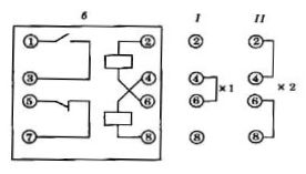
Rice. 2. Wiring diagrams of relay coils
In those cases where a current can flow through the relay for a long time, which is many times higher than the operating setting, the RT40 / 1D relay is used, in which the relay winding is connected to the controlled circuit through an intermediate transformer and a rectifier installed in general body. At currents dangerous in terms of thermal stability, the transformer core is saturated. As a result, the current in the relay winding remains unchanged, although the current in the primary winding of the transformer may continue to increase.
The RT40F relay is used as an organ that reacts to an increase in the current in the controlled circuit above the permissible value when setting from external current harmonics. In practice, the deviation of the shape of the alternating current curve from the sinusoidal can occur both due to the distortion of the shape of the EMF curve. generators, and due to the presence of non-linear elements in alternating current circuits. The RT40F relay contains a special filter that does not pass the current of the third and multiple harmonics in the relay winding. The filter is connected to the secondary winding of the intermediate transformer.
On the basis of the relays of the RT40 series, the voltage relays of the RN50 series are produced. Structurally, the voltage relay of the RN50 series differs from the current relay RT40 in that there is no vibration damper and other coil switching scheme in their design. The winding cross-section of the PH50 voltage relay is smaller than that of the PT40, because the PH50 relay is connected in parallel with the controlled circuit and is constantly energized, and the current relay is in series. The number of turns on a single coil of a current relay varies from one to hundreds, and of a voltage relay from thousands to several thousand.
Table 1. Technical characteristics of the PT40 series current relay
Relay type Setting limits, A Series connection of coils Breaking current, A Thermal resistance, A for a long time within 1 s RT40 / 0.2 0.05…0.2 0.05…0.1 0.55 15 RT40 / 0.6 0.15…0.6 0.15…0.8 1.75 50 RT40 / 2 0.5…2.0 0.5…1.0 4.15 100 RT40 / 6 1.5 …6.0 1.5…3.0 11.0 300 RT40 / 10 2.5…10.0 2.5…5.0 17.0 400 RT40 / 20 5.0…25 5.0…10, 0 19.0 400 RT40 / 50 12.5…50 12.5…25 27.0 500 RT40 / 100 25…100 25…50 27.0 500 RT40 / 200 50…200 50…100 27.0 500