How the gimbal rule works in electrical engineering
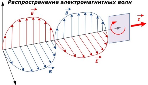
 Widespread in nature electromagnetic fields and waves, carrying interconnected electric and magnetic energy. In space they are located perpendicular to each other.
The main characteristics of the electromagnetic field are:
-
the strength of the electric field, denoted by the index «H»;
-
magnetic induction «B» (or magnetic field strength);
-
electromagnetic potential.
When an electric current passes around the wire, magnetic field… Its intensity (magnetic induction) depends on the magnitude and direction of the current. With the help of the cardan rule, the mutual dependence and the direction of movement of the current and the magnetic induction are determined.
Direction of gimbal rotation
World industrial production has developed a tradition of massive use of threads with right winding direction. Cut into screws, bolts, screws, drills.
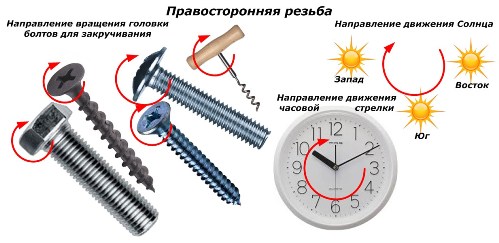
When the head of the fastener is turned clockwise, which repeats the movement of the Sun in the sky, screwing occurs.To disassemble the connection, it is necessary to turn the head in the opposite direction.
Used by electrical engineering and vector algebra, the «Gimbal Rule» assumes exactly this orientation of the thread. Not to be confused with the left hand coil used for example by the gas industry or individual cases of fasteners in mechanical engineering.
Application of the rule
The figure below shows the location of the current conductor, gimbal and magnetic field lines.
1. Determination of the direction of the magnetic induction along the current vector
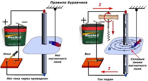
If, parallel to the wire, mentally attach the gimbal so that its translational movement during rotation from the handle coincides with the movement of the current «I» in the wire, then the handle of the gimbal will show the orientation of the lines «B» of the magnetic induction of force.
2. Determining the direction of the current along the magnetic induction vector
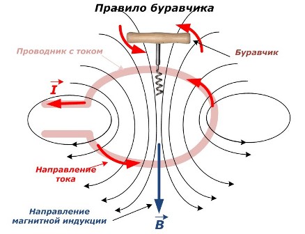
If the orientation of the magnetic induction generated by the current flowing in the ring wire is known, then it is necessary to position the gimbal in such a way that its translational movement coincides with this vector B. Then turning the handle will show the direction of the current inside in the conductor.
Right hand rule
The same relationship between current and magnetic induction can be defined in another way.
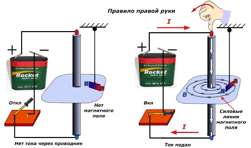
With four fingers of the right hand, fasten the wire. In this case, the large protruding finger should indicate the direction of the current. Then the remaining fingers (from the index finger to the little finger) will show the orientation of the magnetic induction.