Active and reactive resistance, resistance triangle
 Activity and reactivity
The resistance provided by passes and consumers in DC circuits is called Ohmic resistance.
If any wire is included in the AC circuit, then it turns out that its resistance will be slightly higher than in the DC circuit. This is due to a phenomenon called the skin effect (surface effect).
Its essence is as follows. When an alternating current flows through a wire, an alternating magnetic field exists inside it, crossing the wire. The magnetic lines of force of this field induce an EMF in the conductor, however, it will not be the same at different points of the cross section of the conductor: more towards the center of the cross section, and less towards the periphery.
This is due to the fact that the points lying closer to the center are crossed by a large number of force lines. Under the action of this EMF, the alternating current will not be distributed evenly over the entire section of the conductor, but closer to its surface.
This is equivalent to reducing the useful cross-section of the conductor and therefore increasing its resistance to alternating current. For example, a copper wire 1 km long and 4 mm in diameter resists: DC — 1.86 ohms, AC 800 Hz — 1.87 ohms, AC 10,000 Hz — 2.90 ohms.
The resistance offered by a conductor to an alternating current passing through it is called active resistance.
If any consumer does not contain inductance and capacitance (incandescent light bulb, heating device), then it will also be an active AC resistance.
Active resistance — a physical quantity characterizing the resistance of an electric circuit (or its area) to electric current due to irreversible transformations of electric energy into other forms (mainly heat). Expressed in ohms.
Active resistance depends on AC frequencyincreases with its increase.
However, many consumers have inductive and capacitive properties when alternating current flows through them. These consumers include transformers, chokes, electromagnets, capacitors, different types of wires and many others.
When passing through them alternating current it is necessary to take into account not only active, but also reactivity due to the presence of inductive and capacitive properties in the consumer.
It is known that if the direct current passing through each coil is interrupted and closed, then at the same time as the current changes, the magnetic flux inside the coil will also change, as a result of which an EMF of self-induction will occur in it.
The same will be observed in the coil included in the AC circuit, with the only difference that the tock is continuously changing both in magnitude and in and to. Therefore, the magnitude of the magnetic flux penetrating the coil will continuously change and induce EMF of self-induction.
But the direction of the emf of self-induction is always such that it opposes the change in current. So, as the current in the coil increases, the self-induced EMF will tend to slow down the increase in current, and as the current decreases, on the contrary, it will tend to maintain the vanishing current.
It follows that the EMF of self-induction occurring in the coil (conductor) included in the alternating current circuit will always act against the current, slowing down its changes. In other words, the EMF of self-induction can be considered as an additional resistance that, together with the active resistance of the coil, counteracts the alternating current passing through the coil.
The resistance offered by the emf to an alternating current by self-induction is called inductive resistance.
The inductive resistance will be the greater the inductance of the user (circuit) and the higher the frequency of the alternating current. This resistance is expressed by the formula xl = ωL, where xl is the inductive resistance in ohms; L — inductance in henry (gn); ω — angular frequency, where f — current frequency).
In addition to inductive resistance, there is capacitance, due to both the presence of capacitance in the wires and coils and the inclusion of capacitors in the AC circuit in some cases.As the capacitance C of the consumer (circuit) and the angular frequency of the current increase, the capacitive resistance decreases.
Capacitive resistance is equal to xc = 1 / ωC, where xc — capacitive resistance in ohms, ω — angular frequency, C — consumer capacity in farads.
Read more about it here: Reactance in electrical engineering
Resistance triangle
Consider a circuit whose active element resistance r, inductance L and capacitance C.
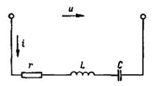
Rice. 1. AC circuit with resistor, inductor and capacitor.
The impedance of such a circuit is z = √r2+ (хl — xc)2) = √r2 + х2)
Graphically, this expression can be depicted in the form of the so-called resistance triangle.
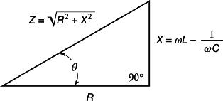
Fig. 2. Resistance triangle
The hypotenuse of the resistance triangle represents the total resistance of the circuit, the legs - active and reactive resistance.
If one of the resistances of the circuit is (active or reactive), for example, 10 or more times less than the other, then the smaller can be neglected, which can be easily checked by direct calculation.