What is an IS barrier and how does it work?
An internal safety barrier or internal protective barrier is an electronic protective device (often of modular design) installed in series in a circuit between an intrinsically safe and an intrinsically safe area of an enterprise, in other words, between an explosion-proof area and an explosion-proof area.
It is obvious that this device, first of all, must itself meet the requirements of its own safety, which is why internal safety barriers are traditionally filled with a compound and such devices are called protective blocks against sparks. Obviously, there is no provision for repairing the spark arrestors — that's the price of safety.
In general, these blocks have a number of advantages: they are universal, inexpensive, easy to install, have small dimensions and a simple modular design, convenient for tight mounting on a DIN rail.
Of the relative disadvantages: the need for reliable grounding of the circuit, limited maximum operating voltage, the protected equipment itself must be qualitatively isolated from the ground.
Regardless of the seeming fancifulness, the protective barrier against sparks is an excellent tool that allows inexpensive, not cumbersome and at the same time reliable, to protect equipment from sparks of an electrical nature. It will become clear later why.
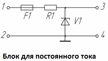
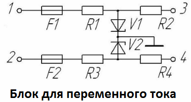
Looking at the circuit diagram of the IS barrier, it is easy to see that the device is quite simple. It contains shunt zener diodes (or a single zener diode) as the main elements, to which a ballast resistor is connected in series on one side and a conventional fuse on the other. This is the so-called shunt-zener spark barrier.
The block works as follows. During normal operation of the equipment Zener diodes closed, current does not flow through them because the voltage across them has not yet exceeded the breakdown voltage.
But at the moment of an emergency situation in the circuit, the voltage of the zener diodes immediately begins to exceed a certain limit — the zener diodes suddenly go into a state of conduction (stabilization mode) — they begin to actively pass current through themselves, bypassing the circuit, preventing The appearance of spark.
A resistor connected in series will limit the current in the protected circuit, and the fuse will prevent an extreme situation - the development of too much current.
Spark barriers manufactured in accordance with GOST R 51330.10-99 are widely used today in enterprises of the chemical, oil and gas industries, where the absence of sparks of any kind is extremely important.
Automated process control systems for the most part contain spark protection devices connected to solenoid valves, two-wire sensors, electro-pneumatic transducers, etc., not to mention simple equipment such as switches, capacitors, chokes-for all elements of electric circuits, on which for one reason or another the appearance of sparks is possible.
Shunt stabilization barriers were invented in the late 1950s specifically for use in process controllers for the chemical industry.
One of the main parameters of the previous and current barriers for protection against sparks was and remains — the flow resistance of the blocks. The low forward resistance allows the use of barriers in combination with sensors with a higher internal resistance and a higher minimum supply voltage.
The high-power resistors and zener diodes used in modern spark arrestors allow today to reduce the resistance of the 24 volt barriers to less than 290 ohms, with the trend towards further reducing on-resistance and increasing power of zener diodes. The limitation is imposed only by the permissible sizes and price of the products.