Compensation installations for reactive power
The article describes the purpose and structural elements of compensating units for reactive electricity.
 Compensation for reactive electrical energy is one of the most effective ways to save energy resources. Modern production is saturated with a large number of engines, welding equipment, power transformers. This consumes a significant amount of reactive power to create magnetic fields in electrical equipment. To reduce the consumption of this type of energy from external networks, compensation units for reactive electrical energy are used. The design, principles of operation and features of their use will be discussed in this article.
The use of capacitor banks to reduce reactive load has been known for a long time. But the inclusion of separate capacitors in parallel with the motors is economically justified only with a significant power of the latter. Typically, the capacitor bank is connected to motors with a power of more than 20-30 kW.
 How to solve the problem of reducing reactive loads in a garment factory where hundreds of low power motors are used? Until recently, in enterprise substations, a fixed set of capacitor banks was connected, which was turned off manually after the end of the work shift. With an obvious inconvenience, such sets could not follow the fluctuations in the power of the loads during the working hours and were inefficient. Modern condensing units can significantly improve efficiency.
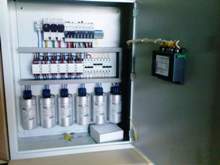
The situation has changed with the advent of specialized microprocessor controllers that measure the value of the reactive power consumed by the loads, calculate the required power value of the capacitor bank and connect (or disconnect) it from the network. Based on such controllers, a wide range of automatic capacitor units for reactive energy compensation. Their power ranges from 30 to 1200 kVar (reactive power is measured in kVars).
The capabilities of the controllers are not limited to measuring and switching capacitor banks. They measure the temperature in the device compartment, measure the current and voltage values, monitor the connection sequence of the batteries and their condition. Controllers can store information about emergency situations and also perform dozens of specific functions, ensuring the reliable operation of the compensation system.
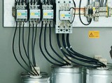
A very important role in the design of reactive power compensation units is played by special contactors that connect and disconnect the capacitor banks on a signal from the controller.Outwardly, they differ little from ordinary magnetic starters used to switch motors.
But the peculiarity of connecting capacitors is such that at the moment when voltage is applied to its contacts, the resistance of the capacitor is practically zero. At capacitor charge an inrush current occurs which often exceeds 10 kA. Such overvoltages have a detrimental effect on both the capacitor itself, the switching device and the external network, causing erosion of the power contacts and creating harmful interference in the electrical wiring.
 To overcome these problems, a special design of contactors has been developed, in which, after applying voltage to the capacitor, its charge passes through the auxiliary current-limiting circuits, and only then the main power contacts are turned on. This design allows you to avoid significant jumps in the charging current of the capacitors, to extend the service life of both the capacitor bank and the special contactor itself.
Finally, the main and most expensive elements of compensation systems are capacitor banks... The requirements imposed on them are quite strict and contradictory. On the other hand, they must be compact and have low internal losses. They must be resistant to frequent charging and discharging processes and have a long service life. But the compactness and low intrinsic losses lead to an increase in charging current spikes, an increase in the temperature inside the product box.
Modern capacitors made by thin-film technology.They use metallized film and hermetically sealed sealant without oil impregnation. This design makes it possible to obtain small-sized products with significant power. For example, cylindrical capacitors with a capacity of 50 kVar have dimensions: diameter 120 mm and height 250 mm.
Similar old-style oil-filled capacitor batteries weighed more than 40 kg and were 30 times larger than modern products. But this miniaturization requires the adoption of measures to cool the area where the capacitor banks are installed. Therefore, in automatic installations, forced blowing by fans of the condenser compartment is mandatory.
In general, the creation of capacitor units requires taking into account a large number of operating parameters: the state of the user's electrical networks, dustiness, the nature of the motor load and many other factors affecting the reliability and efficiency of compensating systems.