Determination of power factor
 In the electric motor, as well as in the transformer, it is necessary to create a magnetic field for operation. This field in alternating current circuits varies in a sinusoidal manner and the energy associated with it flows from the generator to the pantograph for one half period and returns to the generator for the next half period.
This energy is called reactive energy. Its flow manifests itself in the form of an additional current lagging behind the voltage, as shown in Fig. 1, curve c. This current flowing from the generator to the receiver and vice versa does not produce useful work, but only causes additional heating of the wires, that is, additional losses of active energy.
Read more about reactive power here: AC power supply and power losses
The active and reactive currents flowing in the wire add up to a total current that is measured with an ammeter. The product of this total current and voltage is called apparent power.
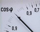
The ratio of active power to total power is called power factor... For the convenience of technical calculations, the power factor is expressed as cosine of conditional angle «phi» (becauseφ).
At different loads, the average power factor is determined over a period of time. To determine the power factor, the readings of the active and reactive meters are used, which allows you to find out the weighted average value of tgφ for the entire period during which energy was consumed.
If we divide the reactive energy consumption by the active energy consumption, we get a value called the "phi" tangent:
tgφ = Wreaction /WAct
Determination of tgφcf, find the value of cosφ.
The power factor value can also be determined from the voltmeter, ammeter and wattmeter readings according to the following formulas:
for single-phase current cosφ = P / UI
for three-phase current cosφ = P /(1.73UlinAzlin)
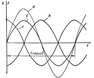
Rice. 1. Phase shift between current and voltage: a — voltage curve, b — active current curve, c — capacitive current curve, d — inductive current curve
The power factor can be determined using a phasor meter. For more details see here: How to measure power factor
Determination of cosφ using an electrical clamp
It is possible to determine the power factor of individual electrical receivers or sections of the network with a slightly changing load using phase meters or wattmeters. However, these methods are difficult because they require interruption of current circuits, and for high-power installations it is necessary to include current transformers.
To measure cosφ without breaking the current circuit, a method using an electrical clamp meter type D90 is used.
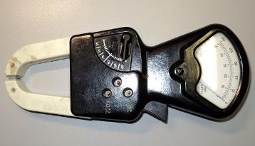
Measuring clamp D90
In three-phase circuits with a balanced load, the power is measured in one phase. For this, one of the wires of the line is covered with the magnetic circuit of the clamp, the generator terminal of the parallel circuit of the wattmeter is connected to the same phase, and the second to the neutral wire. Then, with a Ts91 or Ts4505 type clamp, the current in the phase and the phase voltage are measured.
The power factor is calculated by the formula: cosφ = P / UI
Safety measures must be observed when working with measuring clamps.