Electronic oscilloscopes and their use
 In electronic oscilloscopes, you can observe on the screen the curves of various electrical and impulse processes, varying in frequency from a few hertz to tens of megahertz.
Electronic oscilloscopes can measure various electrical quantities, obtain a family of characteristics of semiconductor devices, hysteresis loops of magnetic materials, determine the parameters of electronic devices, as well as perform many other studies.
Electronic oscilloscopes are connected to an alternating voltage of 127 or 220 V, with a frequency of 50 Hz, and some of them, in addition, can be powered from a source of alternating voltage of 115 or 220 V, a frequency of 400 Hz, or from a source of constant voltage of 24 V , turned on by pressing the «NETWORK» button (fig. 1).
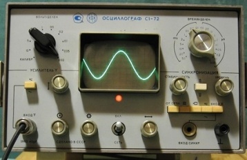
Rice. 1. Front panel of C1-72 electronic oscilloscope
By turning the two corresponding knobs located in the lower left part of the front panel of the device, you can adjust the brightness and focus to get a small glowing spot with a sharp contour on the screen, which cannot be left still for a long time , to avoid damage to the cathode ray tube screen.
This location can be easily moved anywhere on the screen by turning the buttons near which there are double-sided arrows.  It is better, however, before connecting the oscilloscope to a power source, to arrange its controls so that instead of a point on the screen, you immediately get a glowing horizontal line to scan, the brightness, focus and location of which on the screen can be adjusted according to the requirements of the experiment by turning the corresponding knobs.
A test voltage (T) is supplied by a connecting cable to "INPUT Y", which provides its power to the input voltage divider controlled by "AMP Y" and then to the vertical beam deflection amplifier. If before a fixed point shone on the screen, now a vertical strip will appear on it, the length of which is directly proportional to the amplitude of the voltage under study.
Turning on the sawtooth voltage generator built into the oscilloscope, connected to the electron beam tube through a horizontal beam deflection amplifier with gain adjusted by turning the switch knob located in the upper right corner of the front panel of the device, changes the sweep duration and ensures that a curved image appears on your screen (T).
In the event that before turning on the oscilloscope, its controls were set to positions that ensure the appearance of a horizontal cleaning line, the supply of the investigated voltage to "INPUT Y" is accompanied by the appearance on the screen of the same curve and you (T). The immobility of the studied voltage curve is achieved by pressing one of the buttons of the synchronizing unit and by correspondingly turning the STABILITY and LEVEL knobs. A transparent scale covering the CRT screen facilitates the necessary vertical and horizontal measurements.
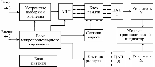
Functional diagram of the oscilloscope:
Most electronic oscilloscopes allow you to simultaneously apply two tested voltages to the Y and X inputs, respectively, if you previously press the «INPUT X» button.
With two sinusoidal voltages with the same frequencies and amplitudes, phase-shifted relative to each other by a, Lissajous figures appear on the screen (Fig. 2), the shape of which depends on the phase shift α = arcsin B / A,
where B is the ordinate of the point of intersection of the Lissajous figure with the vertical axis; A is the ordinate of the top point of the Lissajous figure.
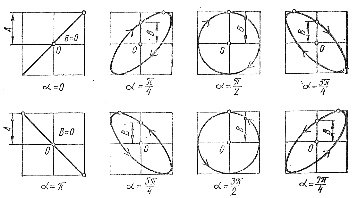
Rice. 2. Lissague figures with two sinusoidal voltages of the same frequencies and equal amplitudes, phase-shifted by α.
The presence of a single beam in the electron beam tube is a significant disadvantage of the oscilloscope, which excludes the simultaneous observation of several processes on the screen, which is eliminated by using an electronic switch.
Two-channel electronic switches have two inputs with one common terminal and one output that connects to the input of the electronic oscilloscope. When the switch operates, its inputs are connected automatically one at a time multivibrator to the Y input, as a result of which both voltage curves fed to the switch inputs are simultaneously observed on the oscilloscope screen. Depending on the switching frequency of the inputs, the curves are displayed on the screen as dashed or solid lines. To obtain the desired scale of the curves, voltage dividers are installed at the inputs of the switches.
Four-channel electronic switches have four bi-clamp inputs with voltage dividers and one output that connects to the Y input of an electronic oscilloscope that allows you to simultaneously see four curves on the screen. Electronic switches usually have knobs to move the waveforms up and down on the oscilloscope screen, allowing them to be positioned according to the requirements of the experiment.
Simultaneous observation of several curves is also possible with multibeam oscilloscopes, where the cathode ray tube has several electrode systems that create and steer beams.
Electronic oscilloscopes allow not only to observe various stationary periodic processes on the screen, but also to photograph oscillograms of various fast processes.
Nowadays, analog oscilloscopes are being replaced by digital storage oscilloscopes, which have more serious functional and metrological capabilities.
Digital storage oscilloscopes are connected to a personal computer or laptop via a parallel LPT or USB port and use the capabilities of a computer to display electrical signals. Most models do not require additional power.
All standard functions of the oscilloscope are performed using special programs that run on a computer, i.e.the computer display is used as an oscilloscope screen. These oscilloscopes have very high sensitivity and bandwidth.
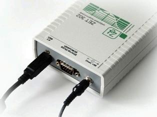
Rice. 3. Storage digital oscilloscope ZET 302
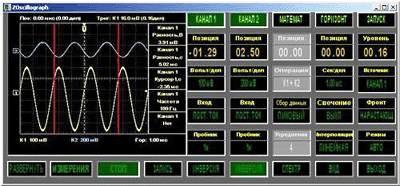
Rice. 4. Program for working with a digital oscilloscope
The storage digital oscilloscope is actually a special attachment to a computer, it takes up much less work space compared to analog models, since the functions of processing and displaying the signal are transferred to a regular computer. The operation of a digital storage oscilloscope is limited only by the operation of a computer.
General control of the sequence of operation of the nodes of the digital oscilloscope is carried out by a microprocessor. Functional Diagram A digital oscilloscope contains a number of computer-specific components. It is primarily a microprocessor, digital control circuits and memory.
Digital oscilloscope software can perform many functions not typical of a light beam oscilloscope, such as averaging a signal to clean it of noise, fast Fourier transformation to obtain spectrograms of the signal, and more.