Electric circuits of direct current and their characteristics
 Properties DC generator are mainly determined by the way the excitation coil is turned on. There are independent, parallel, series and mixed excitation generators:
-
independently excited: the field coil is powered by an external DC source (a battery, a small auxiliary generator called an exciter or rectifier),
-
parallel excitation: the field winding is connected in parallel with the armature winding and the load,
-
series excitation: the field winding is connected in series with the armature winding and the load,
-
with mixed excitation: there are two field windings — parallel and series, the first is connected in parallel with the armature winding, and the second is connected in series with it and the load.
Parallel, series, and mixed-excitation generators are self-excited machines because their field windings are energized by the generator itself.
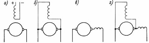
Excitation of DC generators: a — independent, b — parallel, c — series, d — mixed.
All the listed generators have the same device and differ only in the construction of the excitation coils. The coils of independent and parallel excitation are made of wire with a small cross-section, they have a large number of turns, the coil of series excitation is made of wire with a large cross-section, there is a small number of turns.
The properties of DC generators are evaluated by their characteristics: idle, external and control. Below we will look at these characteristics for different types of generators.
An independent generator
A characteristic feature of a generator with independent excitation (Fig. 1) is that its excitation current Iv does not depend on the armature current Ii, but is determined only by the voltage Uv supplied to the excitation coil and the resistance Rv of the excitation circuit.
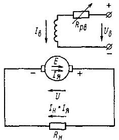
Rice. 1. Schematic diagram of an independent excitation generator
Usually the field current is low and amounts to 2-5% of the rated armature current. To regulate the voltage of the generator, a rheostat for regulation Rpv is often included in the circuit of the excitation winding. The locomotives IV are adjusted by changing the UV voltage.
Idle characteristic of the generator (Fig. 2, a) — the dependence of the voltage Uo at idle on the excitation current Ib in the absence of load Rn, that is, at In = Iya = 0 and at a constant rotational speed n. At no-load, when the load circuit is open, the generator voltage Uo is equal to e. etc. v. Eo = cEFn.
Since when removing the characteristic of idle speed, the speed n is kept unchanged, then the voltage Uo depends only on the magnetic flux F.Therefore, the idle characteristic will be similar to the dependence of the flux F on the excitation current Ia (the magnetic characteristic of the magnetic circuit of the generator).
The no-load characteristic can be easily eliminated experimentally by gradually increasing the excitation current from zero to the value where U0 = 1.25Unom and then decreasing the excitation current to zero. In this case, ascending 1 and descending 2 branches of the characteristic are obtained. The divergence of these branches is due to the presence of hysteresis in the magnetic circuit of the machine. When Iw = 0 in the armature winding, the flux of remanent magnetism induces a remanent d, etc. with Eost, which is usually 2-4% of the nominal voltage Unom.
At low excitation currents, the magnetic flux of the machine is small, therefore in this region the flux and voltage Uo change in direct proportion to the excitation current, and the initial part of this characteristic is a straight line. As the excitation current increases, the magnetic circuit of the generator saturates and the rise in voltage Uo slows down. The greater the excitation current, the stronger the saturation of the machine's magnetic circuit and the slower the voltage U0 increases. At very high excitation currents, the voltage Uo practically stops increasing.
The no-load characteristic allows you to estimate the value of the possible voltage and magnetic properties of the machine. The nominal voltage (indicated in the passport) for general-purpose machines corresponds to the saturated part of the characteristic (the "knee" of this curve).In locomotive generators requiring wide-range voltage regulation, both curvilinear and straight-line unsaturated portions of the characteristic are used.
D. d. C. the machine changes in proportion to the speed n, therefore, for n2 < n1, the idle characteristic lies below the curve for n1. When the direction of rotation of the generator changes, the direction of e changes. etc. c. Is induced in the armature winding, and hence the polarity of the brushes.
An external characteristic of the generator (Fig. 2, b) is the dependence of the voltage U on the load current In = Ia at constant speed n and excitation current Iv. The generator voltage U is always less than its e. etc. c. E by the value of the voltage drop in all windings connected in series in the armature circuit.
As the generator load increases (armature winding current IАЗ САМ — азЗ), the generator voltage decreases for two reasons:
1) due to an increase in the voltage drop in the armature winding circuit,
2) due to a decrease in e. etc. as a result of the demagnetizing action of the armature flux. The magnetic flux of the armature somewhat weakens the main magnetic flux Ф of the generator, which leads to a slight decrease in its e. etc. v. E when loading against e. etc. with Eo at idle.
The change in voltage during the transition from idle mode to rated load in the considered generator is 3 — 8℅ of rated.
If you close the external circuit at a very low resistance, that is, short-circuit the generator, then its voltage drops to zero.The current in the armature winding Ik during a short circuit will reach an unacceptable value at which the armature winding may burn out. In low-power machines, the short-circuit current can be 10-15 times the rated current, in high-power machines, this ratio can reach 20-25.
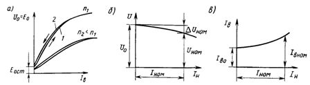
Rice. 2. Characteristics of a generator with independent excitation: a — idle, b — external, c — regulating
The regulating characteristic of the generator (Fig. 2, c) is the dependence of the excitation current Iv on the load current In at constant voltage U and rotation frequency n. It shows how to adjust the excitation current to keep the generator voltage constant as the load changes. Obviously, in this case, as the load increases, it is necessary to increase the excitation current.
The advantages of an independently excited generator are the ability to adjust the voltage over a wide range from 0 to Umax by changing the excitation current and a small change in the generator voltage under load. However, it requires an external DC source to power the field coil.
Generator with parallel excitation.
In this generator (Fig. 3, a) the armature winding current Iya branches into the external load circuit RH (current In) and into the excitation winding (current Iv), the current Iv for machines of medium and high power is 2- 5 % of the rated value of the current in the armature winding. The machine uses the principle of self-excitation, in which the excitation winding is fed directly from the armature winding of the generator. However, self-excitation of the generator is possible only if a number of conditions are met.
1.To start the self-excitation process of the generator, it is necessary to have a residual flux of magnetism in the magnetic circuit of the machine, which induces e in the armature winding. etc. village of Eost. This e. etc. v. provides a flow through the circuit "armature winding - excitation winding" of some initial current.
2. The magnetic flux created by the field coil must be directed in accordance with the magnetic flux of the residual magnetism. In this case, in the process of self-excitation, the excitation current Iv and therefore the magnetic flux Ф of the machine e will increase. etc. v. E. This will continue until, due to the saturation of the magnetic circuit of the machine, the further increase in F and therefore E and Ib stops. The coincidence in the direction of the indicated fluxes is ensured by the correct connection of the excitation winding to the armature winding. If connected incorrectly, the machine demagnetizes (residual magnetism disappears) and e. etc. c. E decreases to zero.
3. The resistance of the RB excitation circuit must be less than a certain limit value called the critical resistance. Therefore, for the fastest excitation of the generator, it is recommended, when the generator is turned on, to fully output the regulating rheostat Rpv connected in series with the excitation coil (see Fig. 3, a). This condition also limits the possible range of regulation of the field current, and hence the voltage of the parallel-excited generator. It is usually possible to reduce the generator voltage by increasing the circuit resistance of the field winding only to (0.64-0.7) Unom.
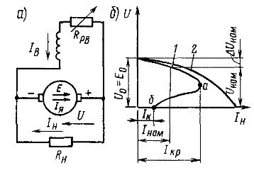
Rice. 3.Schematic diagram of a generator with parallel excitation (a) and external characteristics of generators with independent and parallel excitation (b)
It should be noted that self-excitation of the generator requires the process of increasing its e. etc. with E and excitation current Ib occurred when the machine was idling. Otherwise, due to the low value of Eost and the large internal voltage drop in the armature winding circuit, the voltage applied to the excitation winding may decrease to almost zero and the excitation current cannot increase. Therefore, the load should be connected to the generator only after the voltage at its terminals is close to the nominal one.
When the direction of rotation of the armature changes, the polarity of the brushes changes and therefore the direction of the current in the field winding, in this case the generator is demagnetized.
To avoid this, when changing the direction of rotation, it is necessary to switch the wires connecting the field coil to the armature coil.
External characteristic of the generator (curve 1 in Fig. 3, b) represents the dependence of the voltage U on the load current In at constant values of the speed n and the resistance of the drive circuit RB. It lies below the external characteristic of the independently excited generator (curve 2).
This is explained by the fact that in addition to the same two reasons causing the voltage to decrease with increasing load in an independently excited generator (voltage drop in the armature circuit and the demagnetizing effect of the armature reaction), there is a third reason in considered generator — reduction of the excitation current.
Since the excitation current IB = U / Rv, that is, depends on the voltage U of the machine, then with a decrease in voltage, for these two reasons, the magnetic flux F and e decreases. etc. v. generator E, which leads to a further decrease in voltage. The maximum current Icr corresponding to point a is called critical.
When the armature winding is short-circuited, the current Ic of the parallel-excited generator is small (point b), because in this mode the voltage and the excitation current are zero. Hence the short circuit current is created only by e. etc. from residual magnetism and is (0.4 ... 0.8) Inom .. The external characteristic is divided from point a into two parts: upper — working and lower — non-working.
Usually, not the entire working part is used, but only a certain segment of it. The operation of the section ab of the external characteristic is unstable, in this case the machine goes into the mode corresponding to point b, i.e. in short circuit mode.
The no-load characteristic of the generator with parallel excitation is taken with independent excitation (when the current in the armature Iya = 0), therefore it does not differ in any way from the corresponding characteristic for the generator with independent excitation (see Fig. 2, a). The control characteristic of the generator with parallel excitation has the same shape as the characteristic of the generator with independent excitation (see Fig. 2, c).
Parallel-excited generators are used to power electrical consumers in passenger cars, automobiles, and aircraft, such as generators for driving electric locomotives, diesel locomotives, and railcars, and for charging storage batteries.
Series Excitation Generator
In this generator (Fig.4, a) the excitation current Iw is equal to the load current In = Ia, and the voltage varies significantly when the load current changes. At idle, a small emission is induced in the generator. etc. v. Eri, created by the flow of residual magnetism (Fig. 4, b).
As the load current increases Ii = Iv = Iya, the magnetic flux increases, e.g. etc. p. and generator voltage, this increase, as in other self-excited machines (parallel-excited generator), continues up to a certain limit due to the magnetic saturation of the machine.
As the load current increases above Icr, the generator voltage begins to decrease, since the excitation magnetic flux due to saturation almost stops increasing, and the demagnetizing effect of the armature reaction and the voltage drop in the armature winding circuit IяΣRя continue to increase . Usually the current Icr is much higher than the rated current. The generator can operate stably only on part ab of the external characteristic, i.e. at load currents higher than nominal.
Since in series-excited generators the voltage varies greatly with changes in load and is close to zero during no-load operation, they are unsuitable for supplying most electrical consumers. They are used only with electrical (rheostatic) braking of series-excitation motors, which are then transferred to generator mode.
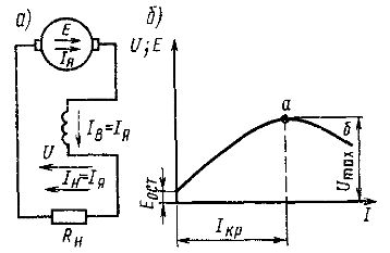
Rice. 4. Schematic diagram of a series excitation generator (a) and its external characteristic (b)
Mixed excitation generator.
In this generator (Fig. 5, a), most often the parallel excitation coil is the main one, and the series one is the auxiliary one.Both coils are of the same polarity and are connected so that the magnetic fluxes produced by them add (concordant switching) or subtract (opposite switching).
A mixed-excitation generator, when its field windings are connected in agreement, enables an approximately constant voltage to be obtained as the load changes. The external characteristic of the generator (Fig. 5, b) can in the first approximation be represented as a sum of characteristics created by each excitation coil.
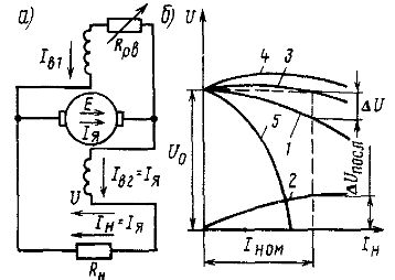
Rice. 5. Schematic diagram of a generator with mixed excitation (a) and its external characteristics (b)
When only one parallel winding is turned on, through which the excitation current Iв1 passes, the generator voltage U gradually decreases with increasing load current In (curve 1). When one series winding is turned on, through which the excitation current Iw2 = In , the voltage U increases with increasing current In (curve 2).
If we choose the number of turns of the series winding so that at the nominal load, the voltage created by it ΔUPOSOL compensated for the total voltage drop ΔU, when the machine operates with only one parallel winding, then it is possible to achieve that the voltage U remains almost unchanged , when the load current changes from zero to the rated value (curve 3). In practice, it varies within 2-3%.
By increasing the number of turns of the series winding, it is possible to obtain a characteristic where the voltage UHOM will have more voltage Uo at idle (curve 4), this characteristic provides compensation for the voltage drop not only in the internal resistance of the armature circuit of the generator, but also in the line connecting it to the load. If the series winding is turned on so that the magnetic flux created by it is directed against the flux of the parallel winding (counter commutation), then the external characteristic of the generator with a large number of turns of the series winding will be steeply falling (curve 5).
Reverse connection of series and parallel field windings is used in welding generators operating under conditions of frequent short circuits. In such generators, in the event of a short circuit, the series winding almost completely demagnetizes the machine and reduces the short circuit current. to a value that is safe for the generator.
Generators with field windings with opposite connections are used on some diesel locomotives as exciters of traction generators, they ensure the constancy of the power delivered by the generator.
Such pathogens are also used on electric direct current locomotives. They feed the field windings of traction motors that operate in regenerative mode during regenerative braking and provide steeply falling external characteristics.
Generator mixed excitation is a typical example of disturbance regulation.
DC generators are often connected in parallel to operate in a common network.A prerequisite for parallel operation of generators with load distribution proportional to the nominal power is the identity of their external characteristics. When using generators with mixed excitation, their series windings for equalizing currents must be connected in a common block by an equalizing wire.