Switching Voltage Regulators
In pulse voltage regulators (converters), the active element (usually a field-effect transistor) operates in pulse mode: the control switch alternately opens and closes, supplying the supply voltage with pulses to the energy-accumulating element. As a result, current pulses are fed through a choke (or through a transformer, depending on the topology of a particular switching regulator), which often acts as an element that accumulates, converts and releases energy in the load circuit.
Pulses have certain time parameters: they follow with a certain frequency and have a certain duration. These parameters depend on the size of the load that is currently supplied by the stabilizer, since it is the average inductor current that charges the output capacitor and actually powers the load connected to it.
In the structure of a pulse stabilizer, three main functional units can be distinguished: a switch, an energy storage device and a control circuit.The first two nodes form a power section, which, together with the third, forms a complete voltage conversion circuit. Sometimes the switch can be made in the same housing as the control circuit.
So the work of the pulse converter is done due to the closing and opening electronic key… When the switch is closed, the energy storage device (choke) is connected to the power source and stores energy, and when it is open, the storage device is disconnected from the source and immediately connected to the load circuit, after which the energy is transferred to the filter capacitor and to the load.
As a result, a certain average value of the voltage acts on the load, which depends on the duration and frequency of repetition of the control pulses. The current depends on the load, the value of which must not exceed the permissible limit for this converter.
PWM and PWM
The principle of stabilization of the output voltage of the pulse converter is based on a continuous comparison of the output voltage with the reference voltage, and depending on the discrepancy of these voltages, the control circuit automatically restores the ratio of the duration of the open and closed states of the switch (it changes the width of the control pulses with pulse width modulation — PWM) or changes the repetition rate of these pulses, keeping their duration constant (by means of pulse frequency modulation — PFM). The output voltage is usually measured with a resistive divider.
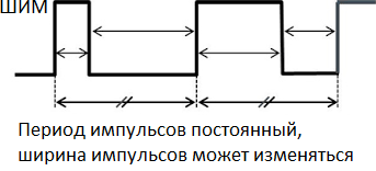
Suppose that the output voltage under load at some point decreases, becomes less than the nominal.In this case, the PWM controller will automatically increase the pulse width, that is, the energy storage processes in the choke will become longer and, accordingly, more energy will be transferred to the load. As a result, the output voltage will return to nominal.
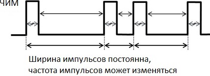
If the stabilization works according to the principle of PFM, then with a decrease in the output voltage under load, the pulse repetition rate will increase. As a result, more parts of energy will be transferred to the load and the voltage will be equal to the required rating. Here it would be appropriate to say that the ratio of the duration of the closed state of the switch to the sum of the duration of its closed and open states is the so-called duty cycle DC.
In general, pulse converters are available with and without galvanic isolation. In this article, we will look at the basic circuits without galvanic isolation: boost, buck and inverting converters. In the formulas, Vin is the input voltage, Vout is the output voltage, and DC is the duty cycle.
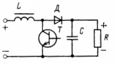
Non-galvanically isolated buck converter-buck converter or step-down converter
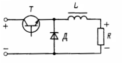
Key T closes. When the switch is closed, diode D is locked, current flows throttle L and across the load R starts to increase. The key opens. When the switch is opened, the current through the choke and through the load, although it decreases, continues to flow, because it cannot disappear instantly, only now the circuit is closed not through the switch, but through the diode that has opened.
The switch closes again.If during the time that the switch was open, the current through the choke did not have time to drop to zero, then now it increases again. So, through the choke and through the load, it acts all the time pulsating current (if there was no capacitor). The capacitor smooths out the ripples so that the load current is almost constant.
The output voltage in a converter of this type is always less than the input voltage, which here is practically split between the choke and the load. Its theoretical value (for an ideal converter—disregarding switch and diode losses) can be found using the following formula:

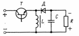
Boost converter without galvanic isolation - boost converter
Switch T is closed. When the switch is closed, the diode D is closed, the current through the inductor L begins to increase. The key opens. Current continues to flow through the inductor, but now through an open diode and the voltage across the inductor is added to the source voltage. The constant voltage across the load R is maintained by capacitor C.
The switch closes, the choke current rises again. The output voltage of a converter of this type is always higher than the input voltage because the voltage across the inductor is added to the source voltage. The theoretical value of the output voltage (for an ideal converter) can be found using the formula:

Inverting converter without galvanic isolation-buck-boost-converter
Switch T is closed. Choke L stores energy, diode D is closed. The switch is open—the choke energizes capacitor C and load R. The output voltage here has negative polarity.Its value can be found (for the ideal case) by the formula:

Unlike linear stabilizers, switching stabilizers have higher efficiency due to less heating of the active elements and therefore require a smaller radiator area. Typical disadvantages of switching stabilizers are the presence of impulse noise in the output and input circuits, as well as longer transients.