Calculations for improving the power factor in a three-phase network
 When calculating the capacitance of a capacitor to improve the power factor in a three-phase network, we will adhere to the same sequence as in the article with examples of calculations in a single-phase network… The value of the power factor is determined by the power formula for three-phase current:
P1 = √3 ∙ U ∙ I ∙ cosφ, cosφ = P1 / (√3 ∙ U ∙ I).
Examples of
1. A three-phase induction motor has the following panel data: P = 40 kW, U = 380 V, I = 105 A, η = 0.85, f = 50 Hz. Star connection of the stator. Suppose that it is difficult to determine the cosφ value of the board, and therefore it is necessary to determine it. To what value will the current decrease after improving the power factor to cosφ = 1 using capacitors? What capacity should the capacitors have? What reactive power will the capacitors (Fig. 1) compensate for?
The clamps of the stator winding are marked: start — C1, C2, C3, ends — C4, C5, C6, respectively.In the following, however, to facilitate communication with the diagrams, the origin will be labeled A, B, C, and the ends X, Y, Z.
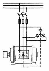
Rice. 1.
Motor power P1 = P2 / η = 40000 / 0.85 ≈47000 W,
where P2 is the net power that is listed on the motor nameplate.
cosφ = P1 / (√3 ∙ U ∙ I) = 47000 / (√3 ∙ 380 ∙ 105) = 0.69.
After improving the power factor to cosφ = 1, the input power will be:
P1 = √3 ∙ U ∙ I ∙ 1
and the current will drop to
I1 = P1 / (√3 ∙ U) = 47000 / (1.73 ∙ 380) = 71.5 A.
This is the active current at cosφ = 0.69 since
Ia = I ∙ cosφ = 105 ∙ 0.69 = 71.5 A.
In fig. 1 shows the inclusion of capacitors to improve cosφ.
Capacitor voltage Uph = U / √3 = 380 / √3 = 220 V.
The phase magnetizing current is equal to the linear magnetizing current: IL = I ∙ sinφ = 105 ∙ 0.75 = 79.8 A.
The capacitive resistance of the capacitor, which must provide the magnetizing current, will be: xC = Uph / IL = 1 / (2 ∙ π ∙ f ∙ C).
Therefore, the capacitance of the capacitor C = IC / (Uph ∙ 2 ∙ π ∙ f) = 79.8 / (220 ∙ 3.14 ∙ 100) = 79.800 / (22 ∙ 3.14) ∙ 10 ^ (- 6) = 1156.4 μF.
A block of capacitors with a total capacity of C = 3 ∙ 1156.4≈3469 μF must be connected to a three-phase motor to improve the power factor to cosφ = 1 and at the same time reduce the current from 105 to 71.5 A.
The total reactive power compensated by capacitors, which in the absence of capacitors is taken from the network, Q = 3 ∙ Uph ∙ IL = 3 ∙ 220 ∙ 79.8≈52668 = 52.66 kvar.
In this case, the motor consumes active power P1 = 47 kW only from the network.
In fig.2 shows a block of capacitors connected in a delta and connected to the terminals of a three-phase motor whose winding is also connected in a delta. This connection of capacitors is more advantageous than the connection shown in fig. 1 (see the conclusion of calculation 2).
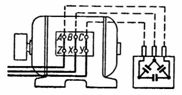
Rice. 2.
2. A small power plant feeds a three-phase network with a current I = 250 A at a network voltage U = 380 V and a network power factor cosφ = 0.8. The improvement of the power factor is achieved by capacitors which are connected in delta according to the diagram in fig. 3. It is necessary to determine the value of the capacitance of the capacitors and the compensated reactive power.
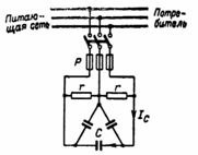
Rice. 3.
Apparent power S = √3 ∙ U ∙ I = 1.73 ∙ 380 ∙ 250 = 164.3 kVA.
Determine the active power at cosφ = 0.8:
P1 = √3 ∙ U ∙ I ∙ cosφ = S ∙ cosφ≈164.3 ∙ 0.8 = 131.5 W.
Reactive power to be compensated at cosφ = 0.8
Q = S ∙ sinφ≈164.3 ∙ 0.6 = 98.6 kvar.
Therefore, the linear magnetizing current (Fig. 3) IL = I ∙ sinφ = Q / (√3 ∙ U) ≈150 A.
Magnetizing (capacitive) phase current ICph = Q / (3 ∙ U) = 98580 / (3 ∙ 380) = 86.5 A.
The capacitor current can be determined in another way by the magnetizing (reactive) current in the circuit:
IL = I ∙ sinφ = 250 ∙ 0.6 = 150 A,
ICph = ILph = IL / √3 = 150 / 1.73 = 86.7 A.
When connected in a delta, each group of capacitors has a voltage of 380 V and a phase current ICph = 86.7 A.
I = ICf = U / xC = U / (1⁄ (ω ∙ C)) = U ∙ ω ∙ C.
Therefore, C = IC / (U ∙ 2 ∙ π ∙ f) = 86.7 / (300 ∙ π ∙ 100) = 726 μF.
The total capacitance of the capacitor bank is C3 = 3 ∙ 726 = 2178 μF.
The connected capacitors make it possible to use the entire power of the power plant S = 164.3 kVA in the form of net power.Without operation capacitors, only active power of 131.5 kW is used at cosφ = 0.8.
The compensated reactive power Q = 3 ∙ U ∙ IC = 3 ∙ ω ∙ C ∙ U ^ 2 increases in proportion to the square of the voltage. Therefore, the required capacity of the capacitors, and hence the cost of the capacitors, is lower because the voltage is higher.
Resistances r in fig. 3 are used to gradually discharge capacitors when they are disconnected from the network.