Calculation of the heating element

To determine one of the main parameters of the wire of the heating element — diameter d, m (mm), two methods of calculation are used: according to the allowable specific surface power PF and using the table of current loads.
Permissible specific surface power PF= P⁄F,
where P is the power of the wire heater, W;
F = π ∙ d ∙ l — heater area, m2; l — wire length, m.
According to the first method
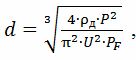
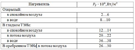
where ρd — electrical resistance of the wire material at actual temperature, Ohm • m; U is the heater wire voltage, V; PF — permissible values of specific surface power for different heaters:
The second method uses a table of current loads (see Table 1) compiled from experimental data. To use the indicated table, it is necessary to determine the calculated heating temperature Tp related to the actual (or permissible) temperature of the conductor Td by the ratio:
Tr = Km ∙ Ks ∙ Td,
where Km is the installation factor, taking into account the deterioration of the cooling conditions of the heater due to its construction; Kc is the ambient factor, considering the improvement of the heater cooling conditions compared to a stationary air environment.
For a heating element made of wire twisted in a spiral, Km = 0.8 … 0.9; the same, with a ceramic base Km = 0.6 ... 0.7; for a wire of heating plates and some heating elements Km = 0.5 ... 0.6; for a conductor from an electric floor, soil and heating elements Km = 0.3 ... 0.4. A smaller value of Km corresponds to a heater with a smaller diameter, a larger value to a larger diameter.
When operating under conditions other than free convection, Kc = 1.3 … 2.0 is taken for heating elements in the air stream; for elements in still water Kc = 2.5; in the water flow — Kc = 3.0 … 3.5.
If the voltage Uph and the power Pf of the future (designed) heater are set, then its current (per phase)
Iph = Pph⁄Uph
According to the calculated value of the current of the heater for the necessary calculated temperature of its heating according to table 1, the required diameter of the nichrome wire d is found and the required length of the wire, m, for the manufacture of the heater is calculated:

where d is the selected wire diameter, m; ρd is the specific electrical resistance of the conductor at the actual heating temperature, Ohm • m,
ρd = ρ20 ∙ [1 + αp ∙ (Td-20)],
where αр — temperature coefficient of resistance, 1/OS.
To determine the parameters of the nichrome spiral, take the average diameter of the turns D = (6 … 10) ∙ d, the pitch of the spiral h = (2 … 4) ∙ d,
number of turns
helix length lsp = h ∙ n.
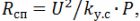
When calculating the heating elements, it should be remembered that the resistance of the spiral wire after pressing the heating element
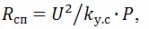
where k (y.s) is a coefficient that takes into account the reduction in the resistance of the spiral; according to experimental data, k (s) = 1.25. It should also be taken into account that the specific surface power of the spiral wire is 3.5 ... 5 times greater than the specific surface power of the tubular heating element.
In practical calculations of the heating element, first determine the temperature of its surface Tp = To + P ∙ Rt1,
where It is the ambient temperature, ° C; P is the power of the heating element, W; RT1 — thermal resistance at the pipe — medium interface, ОC / W.
Then the temperature of the winding is determined: Tsp = To + P ∙ (Rt1 + Rt2 + Rt3),
where Rt2 is the thermal resistance of the pipe wall, ОC / W; RT3 — thermal resistance of the filler, ОC / W; Rp1 = 1⁄ (α ∙ F), where α is the heat transfer coefficient, W / (m ^ 2 • ОС); F — area of the heater, m2; Rt2 = δ⁄ (λ ∙ F), where δ is the wall thickness, m; λ — thermal conductivity of the wall, W / (m • ОС).
For more information on the device of the heating elements, see here: Heating elements. Device, selection, operation, connection of heating elements
Table 1. Table of current loads

Example 1. Calculate the electric heater in the form of a wire spiral according to the allowable specific surface power PF.
Condition.Heater power P = 3.5 kW; supply voltage U = 220 V; wire material — nichrome Х20Н80 (an alloy of 20% chromium and 80% nickel), therefore the specific electrical resistance of the wire ρ20 = 1.1 ∙ 10 ^ ( — 6) Ohm • m; temperature coefficient of resistance αр = 16 ∙ 10 ^ (- 6) 1 /ОС; the spiral is open, in metallic form, the working temperature of the spiral is Tsp = 400 ОC, PF= 12 ∙ 10 ^ 4 W / m2. Determine d, lp, D, h, n, lp.
Answer. Coil resistance: R = U ^ 2⁄P = 220 ^ 2⁄3500 = 13.8 ohms.
Specific electrical resistance at Tsp = 400 OS
ρ400 = 1.1 ∙ 10 ^ (- 6) ∙ [1 + 16 ∙ 10 ^ (- 6) ∙ (400-20)] = 1.11 ∙ 10 ^ (- 6) Ohm • m.
Find the diameter of the wire:
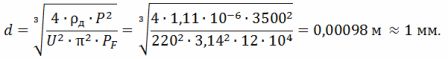
From the expression R = (ρ ∙ l) ⁄S we get l⁄d ^ 2 = (π ∙ R) ⁄ (4 ∙ ρ), whence the length of the wire

The average diameter of the spiral turn is D = 10 ∙ d = 10 ∙ 0.001 = 0.01 m = 10 mm. Spiral pitch h = 3 ∙ d = 3 ∙ 1 = 3 mm.
The number of turns of the spiral
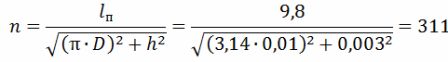
The length of the helix is lsp = h ∙ n = 0.003 ∙ 311 = 0.933 m = 93.3 cm.
Example 2. Structurally calculate the wire resistance heater when determining the wire diameter d using the table of current loads (see table 1).
Condition. Wire heater power P = 3146 W; supply voltage U = 220 V; wire material — nichrome Х20Н80 ρ20 = 1.1 ∙ 10 ^ ( — 6) Ohm • m; αp = 16 ∙ 10 ^ (- 6) 1 / ℃; open helix located in the air stream (Km = 0.85, Kc = 2.0); permissible operating temperature of the conductor Td = 470 ОС.
Determine the diameter d and the length of the wire lp.
Answer.
Tr = Km ∙ Ks ∙ Td = 0.85 ∙ 2 ∙ 470 OS = 800 OS.
The design heater current I = P⁄U = 3146⁄220 = 14.3 A.
According to the table of current loads (see table 1) at Tр = 800 ОС and I = 14.3 A, we find the diameter and cross-section of the wire d = 1.0 mm and S = 0.785 mm2.
Wire length lp = (R ∙ S) ⁄ρ800,
where R = U ^ 2⁄P = 220 ^ 2⁄3146 = 15.3 Ohm, ρ800 = 1.1 ∙ 10 ^ (- 6) ∙ [1 + 16 ∙ 10 ^ (- 6) ∙ (800-20) ] = 1.11 ∙ 10 ^ (- 6) Ohm • m, lp = 15.3 ∙ 0.785 ∙ 10 ^ (- 6) ⁄ (1.11 ∙ 10 ^ (- 6)) = 10.9 m.
Also, if necessary, similar to the first example, D, h, n, lsp can be defined.
Example 3. Determine the allowable voltage of the tubular electric heater (TEN).
Condition... The coil of the heating element is made of nichrome wire with diameter d = 0.28 mm and length l = 4.7 m. The heating element is in still air with a temperature of 20 °C. Characteristics of nichrome: ρ20 = 1.1 ∙ 10 ^ (- 6) Ohm • m; αр = 16 ∙ 10 ^ (- 6) 1 / ° C. The length of the active part of the housing of the heating element is La = 40 cm.
The heating element is smooth, outer diameter dob = 16 mm. Heat transfer coefficient α = 40 W / (m ^ 2 ∙ ° C). Thermal resistances: filler RT3 = 0.3 ОС / W, housing walls Rт2 = 0.002 ОС / W.
Determine what maximum voltage can be applied to the heating element so that its coil temperature Tsp does not exceed 1000 ℃.
Answer. Heating element temperature of the heating element
Tsp = To + P ∙ (Rt1 + Rt2 + Rt3),
where It is the ambient air temperature; P is the power of the heating element, W; RT1 — contact thermal resistance of the pipe-medium interface.
Power of the heating element P = U ^ 2⁄R,
where R is the resistance of the heating coil.Therefore, we can write Tsp-To = U ^ 2 / R ∙ (Rt1 + Rt2 + Rt3), whence the voltage on the heating element
U = √ ((R ∙ (Tsp-To)) / (Rt1 + Rt2 + Rt3)).
Find R = ρ ∙ (4 ∙ l) ⁄ (π ∙ d ^ 2),
where ρ1000 = ρ20 ∙ [1 + αp ∙ (T-20)] = 1.1 ∙ 10 ^ (- 6) ∙ [1 + 16 ∙ 10 ^ (- 6) ∙ (1000-20)] = 1.12 ∙ 10 ^ ( — 6) Ohm • m.
Then R = 1.12 ∙ 10 ^ (- 6) ∙ (4 ∙ 4.7) ⁄ (3.14 ∙ (0.28 ∙ 10 ^ (- 3)) ^ 2) = 85.5 Ohm.
Contact thermal resistance RT1 = 1⁄ (α ∙ F),
where F is the area of the active part of the shell of the heating element; F = π ∙ dob ∙ La = 3.14 ∙ 0.016 ∙ 0.4 = 0.02 m2.
Find Rt1 = 1⁄ (40 ∙ 0.02 = 1.25) OC / W.
Determine the voltage of the heating element U = √ ((85.5 ∙ (1000-20)) / (1.25 + 0.002 + 0.3)) = 232.4 V.
If the nominal voltage indicated on the heating element is 220 V, then the overvoltage at Tsp = 1000 OS will be 5.6% ∙ Un.