Classification of electrical networks
Electric networks are classified according to a number of indicators that characterize both the network as a whole and individual transmission lines (PTL).
By the nature of the current
AC and DC networks are distinguished by current.
Three-phase AC 50 Hz has several advantages over DC:
-
the ability to transform from one voltage to another in a wide range;
-
the ability to transmit large powers over long distances, which is achieved. This is achieved by transforming the voltage of the generators to a higher voltage for transmitting electricity along the line and converting the high voltage back to a low voltage at the receiving point. In this method of power transmission, the losses in the line are reduced because they depend on the current in the line, and the current for the same power is smaller, the higher the voltage;
-
with three-phase alternating current, the construction of asynchronous electric motors is simple and reliable (no collector). The construction of a synchronous alternator is also simpler than a DC generator (no collector, etc.);
Disadvantages of AC are:
-
the need to generate reactive power, which is needed mainly to create magnetic fields of transformers and electric motors. Fuel (in TPP) and water (in HPP) are not consumed to generate reactive energy, but the reactive current (magnetizing current) flowing through the lines and windings of the transformers is useless (in the sense of using lines to transmit active energy) it overloads them, causes losses of active power in them and limits the transmitted active power. The ratio of reactive power to active power characterizes the power factor of the installation (the lower the power factor, the worse the electrical networks are used);
-
capacitor banks or synchronous compensators are often used to increase the power factor, which makes AC installations more expensive;
-
the transmission of very large powers over long distances is limited by the stability of the parallel operation of the power systems between which power is transmitted.
Advantages of direct current include:
-
absence of a reactive current component (full use of lines is possible);
-
convenient and smooth adjustment in a wide range of the number of revolutions of DC motors;
-
high starting torque in serial motors, which have found wide application in electric traction and cranes;
-
the possibility of electrolysis, etc.
The main disadvantages of DC are:
-
impossibility of conversion by simple means of direct current from one voltage to another;
-
the impossibility of creating high-voltage (HV) direct current generators for power transmission over relatively long distances;
-
the difficulty of obtaining direct current HV: for this purpose it is necessary to rectify the alternating current of the high voltage and then at the point of reception turn it into three-phase alternating current. The main application is derived from three-phase alternating current networks. With a large number of single-phase electrical receivers, single-phase branches are made from a three-phase network. The advantages of a three-phase AC system are:
-
the use of a three-phase system to create a rotating magnetic field makes it possible to implement simple electric motors;
-
in a three-phase system, the power loss is less than in a single-phase system. The proof of this statement is given in Table 1.
Table 1. Comparison of a three-phase system (three-wire) with a single-phase (two-wire)
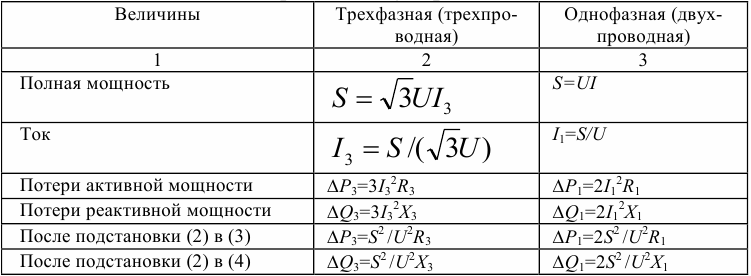
As can be seen from the table (rows 5 and 6), dP1= 2dP3 and dQ1= 2dQ3, i.e. power losses in a single-phase system at the same power S and voltage U are twice as large. However, in a single-phase system there are two wires, and in a three-phase system - three.
In order for the metal consumption to be the same, it is necessary to reduce the cross-section of the conductors of the three-phase line compared to the single-phase line by 1.5 times. The same number of times will be greater resistance, i.e. R3= 1.5R1... Substituting this value in the expression for dP3, we get dP3 = (1.5S2/ U2) R1, i.e. active power losses in a single-phase line are 2 / 1.5 = 1.33 times more than in a three-phase one.
DC usage
DC networks are built to power industrial enterprises (electrolysis workshops, electric furnaces, etc.), urban electric transport (tram, trolleybus, subway). For more details see here: Where and how DC is used
Electrification of railway transport is carried out on both direct and alternating current.
Direct current is also used to transmit energy over long distances, since the use of alternating current for this purpose is associated with the difficulty of ensuring stable parallel operation of power plant generators. In this case, however, only a transmission line operates on direct current, at the supply end of which the alternating current is converted to direct current, and at the receiving end the direct current is reversed to alternating current.
Direct current can be used in transmission networks with alternating current to organize the connection of two electrical systems in the form of direct current — transmission of constant energy with zero length, when two electrical systems are connected to each other through a rectifier-transformer unit. At the same time, frequency deviations in each of the electrical systems practically do not affect the transmitted power.
Research and development is currently underway on pulsed current power transmission, where power is transmitted simultaneously by alternating current and direct current over a common power line. In this case, it is intended to impose on all three phases of the AC transmission line some constant voltage with respect to earth, created by means of transformer installations at the ends of the transmission line.
This method of power transmission enables better use of power line insulation and increases its carrying capacity compared to alternating current transmission, and also facilitates the selection of power from power lines compared to direct current transmission.
By voltage
By voltage, electrical networks are divided into networks with a voltage of up to 1 kV and over 1 kV.
Each electrical network is characterized by rated voltage, which ensures the normal and most economical operation of the equipment.
Distinguish the nominal voltage of generators, transformers, networks and electrical receivers. The nominal voltage of the network coincides with the nominal voltage of the energy consumers, and the nominal voltage of the generator, according to the conditions of compensation for voltage losses in the network, is taken 5% higher than the nominal voltage of the network.
The rated voltage of a transformer is set for its primary and secondary windings at no load. Due to the fact that the primary winding of the transformer is a receiver of electricity, for the step-up transformer its nominal voltage is taken equal to the nominal voltage of the generator, and for the step-down transformer - the nominal voltage of the network.
The voltage of the secondary winding of the transformer supplying the network under load must be 5% higher than the nominal voltage of the network. Since there is a voltage loss in the transformer itself under load, the rated voltage (ie open circuit voltage) of the secondary winding of the transformer is taken 10% higher than the rated mains voltage.
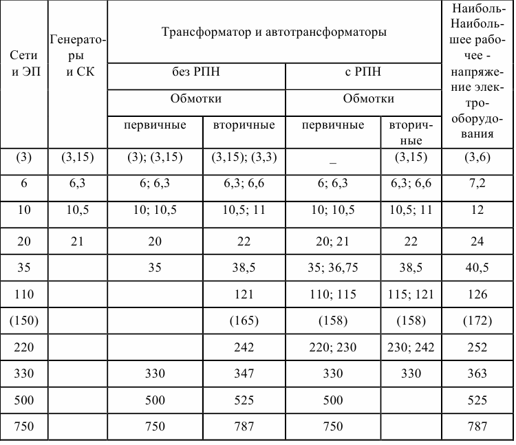
Table 2 shows the nominal phase-to-phase voltages of three-phase electrical networks with a frequency of 50 Hz. Electric networks by voltage are conditionally divided into low (220–660 V), medium (6–35 kV), high (110–220 kV), ultrahigh (330–750 kV) and ultrahigh (1000 kV and higher ) voltage networks.
Table 2. Standard voltages, kV, according to GOST 29322–92
In transport and industry, the following constant voltages are used: for an overhead network powering trams and trolleybuses — 600 V, subway cars — 825 V, for electrified railway lines — 3300 and 1650 V, open-pit mines are served by trolleybuses and electric locomotives powered from contact networks 600, 825, 1650 and 3300 V, underground industrial transport uses a voltage of 275 V. Arc furnace networks have a voltage of 75 V, electrolysis plants 220-850 V.
By design and location
Aerial and cable networks, wiring and wires differ in design.
By location, networks are divided into external and internal.
External networks are implemented with bare (non-insulated) wires and cables (underground, underwater), internal - with cables, insulated and bare wires, buses.
By nature of consumption
According to the nature of consumption, urban, industrial, rural, electrified railway lines, oil and gas pipelines and electrical systems are distinguished.
By appointment
The diversity and complexity of electrical networks has led to the lack of a unified classification and the use of different terms when classifying networks by purpose, role and functions performed in the power supply scheme.
NSElectrical networks are divided into backbone and distribution networks.
The spine is called an electrical network that unites power plants and ensures their functioning as a single control object, while supplying energy from power plants. Branch called a power grid. providing electricity distribution from a power source.
In GOST 24291-90, electrical networks are also divided into backbone and distribution networks.In addition, urban, industrial and rural networks are distinguished.
The purpose of distribution networks is the further distribution of electricity from the substation of the backbone network (partly also from the distribution voltage buses of power plants) to the central points of urban, industrial and rural networks.
The first stage of public distribution networks is 330 (220) kV, the second - 110 kV, then electricity is distributed through the power supply network to individual consumers.
According to the functions they perform, backbone, supply and distribution networks are distinguished.
Main networks 330 kV and above perform the functions of forming unified energy systems.
The power supply networks are intended for the transmission of electricity from the substations of the highway network and partially the 110 (220) kV buses of power plants to the central points of the distribution networks — regional substations. Delivery networks usually closed. Previously, the voltage of these networks was 110 (220) kV, recently the voltage of electrical networks, as a rule, is 330 kV.
Distribution networks are intended for the transmission of electricity over short distances from the low-voltage buses of district substations to urban industrial and rural consumers. Such distribution networks are usually open or operate in open mode. Previously, such networks were carried out at a voltage of 35 kV and lower, and now - 110 (220) kV.
Electricity networks are also subdivided into local and regional and, in addition, supply and distribution networks. Local networks include 35 kV and lower, and regional networks — 110 kV and higher.
Eating is a line passing from a central point to a distribution point or directly to substations without distributing electricity along its length.
Branch a line is called, to which several transformer substations or the entrance to consumer electrical installations are connected along their length.
According to the purpose in the power scheme, networks are also divided into local and regional.
To the locals include networks with low load density and voltage up to and including 35 kV. These are urban, industrial and rural networks. Short-length 110 kV deep bushings are also classified as local networks.
District electrical networks cover large areas and have a voltage of 110 kV and above. Through regional networks, electricity is transmitted from power plants to places of consumption, and also distributed between regional and large industrial and transport substations that feed local networks.
Regional networks include the main networks of electrical systems, the main transmission lines for intra- and inter-system communication.
Core networks provide communication between power plants and with regional consumer centers (regional substations). They are carried out according to complex multi-circuit schemes.
Trunk power lines intra-system communication provides communication between separately located power plants with the main grid of the electricity system, as well as communication of remote large users with central points. This is usually an overhead line 110-330 kV and larger with a long length.
According to their role in the power supply scheme, power supply networks, distribution networks and main networks of power systems differ.
Nourishing are called the networks through which the energy is supplied to the substation and RP, distribution — networks to which electrical or transformer substations are directly connected (usually these are networks up to 10 kV, but often branched networks with higher voltages also refer to distribution networks if a large number of receiving substations are connected to them). To the main networks include networks with the highest voltage, over which the most powerful connections are made in the electrical system.