Electrodynamic forces in live parts of structures and devices
 Parts of electrical equipment and distribution devices under voltage, when current flows through them, are exposed to electrodynamic forces... As you know, such forces act on any current-carrying conductor located in magnetic field.
The magnitudes of these forces for switchgear elements and devices of simple configuration can be determined based on Biot-Savard's law:

where (H, l) is the angle formed by the direction of the current and the direction of the magnetic field; with parallel wires is 90 °.
If two parallel conductors move in a current and a conductor with a current i1 is in a magnetic field with a current i2 of intensity H = 0.2 • i2 / a, then the magnitude of the force acting between them will be equal to
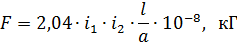
where i1 and i2 are the currents of the first and second wires, and; a is the distance between the axes of the wires, cm; l — wire length, see
The force acting between the wires attracts them to each other with the same direction of current in them and repels them in different directions.
The largest value of these electrodynamic forces is determined by the maximum possible short-circuit current, i.e. Short-circuit current iy. Therefore, the initial moment of the short circuit (t = 0.01 sec) is the most dangerous in terms of the magnitude of the dynamic forces.
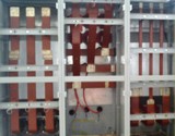
When a short-circuit current flows through the circuit breaker or when it is connected to an existing network short circuit its individual parts — bushings, conducting rods, sleepers, rods, etc., as well as the corresponding tires and busbars — are subjected to a sudden mechanical load, which has the character of an impact.
In modern high-power electrical systems at voltages of 6-20 kV, short-circuit currents can reach values up to 200-300 ka and more, while electrodynamic forces reach several tons per bus (or buses) 1 -1.5 m long...
Under such conditions, the insufficient mechanical strength of one or another element of the electrical equipment can cause further development of the accident and cause serious damage to the switchgear. Therefore, for the reliable operation of any electrical installation, all its elements must have electrodynamic stability (adequate mechanical strength), that is, withstand the effects of a short circuit.
When determining the electrodynamic forces according to the above formula, it is assumed that the current flows along the axis of round wires, the diameter of which does not affect the magnitude of the forces. It should be noted that the size and shape of the cross-section of the wires at large distances between them have no noticeable effect on the magnitude of the electrodynamic forces.
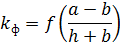
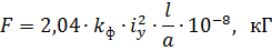
If the wires are in the form of rectangular strips and are located at a small distance from each other, when the distance in the light is less than the perimeter of the strip, then the dimensions of their cross-section can have a significant influence on the electrodynamic forces. This influence of the cross-sectional dimensions of the conductor is taken into account in the calculations using the form factor.
If live wires belong to the same circuit and i1 = i2 = iy then the largest interaction force will be equal to
With various other simple and complex forms of wires, it is more convenient to use the principle of the increase of electromagnetic energy and the resulting dependencies.
Such simple dependences can be obtained by considering two interacting circuits L1 and L2 carried by currents i1 and i2. The supply of electromagnetic energy for these circuits will be as follows:
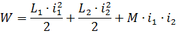
If, as a result of the interaction of currents i1 and i2, the loop of the system is deformed under the action of electrodynamic forces in any direction by the amount dx, then the work done by the field strength Fx will be equal to the increase in the supply of electromagnetic energy to the system by the quantity dW:

where:

In cases where in practice it is necessary to determine the electrodynamic force between parts or sides of the same circuit with inductance L1-L, the interaction force will be:
Using this expression, we determine the electrodynamic forces for several simple but practically important cases:
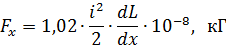
1. Parallel wires with a jumper.
In oil circuit breakers and disconnectors, a circuit is formed with this configuration.
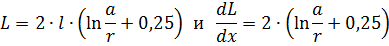
The inductance of the loop will be
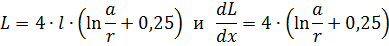
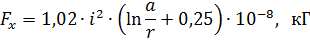
therefore the force acting on the partition is
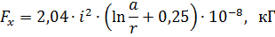
where a is the distance between the axes of the wires; r is the radius of the wire.
This expression gives the electrodynamic forces acting on the switch beam or switch blade. They facilitate the movement of the oil circuit breaker stroke when the current is off and repel it when it is on.
In order to have an idea of the magnitude of the resulting forces, it is enough to say that, for example, in the VMB-10 power circuit breaker with a short-circuit current of 50 kA, the force acting on the traverse is about 200 kg.
2. A conductor bent at right angles.
Such an arrangement of conductors is usually used in switchgear to arrange the busbars of the approaches to and after the apparatus, it is also found in bushing disconnectors.
The inductance of the conductor forming such a circuit will be:
Therefore, the site effort will be determined as in the previous case:
where a is the length of a movable element, for example a disconnector blade.
Under the action of the current, the wire bent at an angle tends to straighten, and if one side of it is movable, for example, the blade of the disconnector, then measures must be taken against possible spontaneous tripping during a short circuit.