Application and installation of flat wires
Field of application of flat wires
 Flat wires are mainly used in public, administrative, utility, engineering and laboratory and other similar buildings. For hidden laying of group lighting lines in buildings with mass construction, flat wires of types APPVS, APN, APPPS, etc. should be used. Flat wires with copper conductors should be used in residential and public buildings.
It is allowed to lay flat wires in dry, wet and damp rooms.
Laying is not allowed:
a) in explosive premises, especially damp, with a chemically active environment,
b) directly on unpainted wooden foundations - in children's and medical facilities, entertainment enterprises, palaces of culture, clubs, schools,
c) on stages and in auditoriums of entertainment enterprises,
d) open laying of wires in fire-hazardous rooms and ceilings.
Due to the lack of dust-proof lighting boxes for flat wires, they are practically impossible to use in dusty rooms.
It is allowed to lay flat wires in separate sections in plastic and steel pipes.
Brands with flat wire
For hidden laying, wires without a bonding film should mainly be used - APPVS, PPVS, APPPS, PPPS, for open laying APPV, PPV, APPP, PPP, APN wires are provided, and for laying on wooden and other combustible bases - APPR.
Allowed open transaction methods
Open wiring is done:
• directly on walls, partitions and ceilings covered with dry plaster or wet plaster,
• on non-combustible walls and partitions pasted with wallpaper (directly above and below the wallpaper),
• on wooden walls and partitions lined with asbestos sheets with a thickness of 3 mm (APPR wires can be laid directly on wooden bases),
• on wheels and insulators (in rural areas only).
Acceptable hidden wiring methods
Concealed wiring is allowed:
• on non-flammable walls and partitions to be plastered or covered with wet plaster, — in a plaster groove or under a layer of wet plaster,
• on non-combustible walls and partitions covered with dry gypsum plaster — in a plaster groove in the thickness of the wall or partition, or in a continuous layer of alabaster asphalt, or under a layer of asbestos sheet,
• on wooden walls covered with wet plaster walls and partitions — under a layer of plaster with a lining for conductors of a layer of asbestos sheets with a thickness of at least 3 mm or according to a contour of plaster with a thickness of at least 5 mm, while if asbestos or gypsum are laid over shingles or the shingles is cut across the width of the asbestos seal, the asbestos or plaster must protrude at least 5mm on each side of the wire,
• on wooden walls and partitions covered with a layer of dry plaster — in the gap between the wall and the plaster in a continuous layer of alabaster asphalt or between two layers of sheet asbestos with a thickness of at least 3 mm, a layer of alabaster asphalt or asbestos must protrude at least 5 mm on each side of the wire,
• in ducts and cavities of building structures in accordance with the "Instructions for the implementation of electrical wiring in the ducts of building structures manufactured in factories of home-building plants and the construction industry",
• under a layer of wet plaster on ceilings made of non-combustible slabs,
• in the gaps between reinforced concrete slabs with their subsequent embedding with alabaster mortar,
• in furrows specially left in reinforced concrete slabs of large dimensions, with their subsequent embedding with alabaster mortar,
• over non-combustible floor slabs under the clean floor of the next floor, including in the attic, over the ceiling slabs of the upper floor, under a 10 mm thick layer of cement or alabaster or in pipes,
• under a layer of wet plaster on floors made of combustible boards with a seal between the floor and the conductors on a layer of asbestos sheet or according to the plaster layer, when dry gypsum plaster is used, the conductors must be laid between two layers of asbestos or in a continuous layer of alabaster wool with a layer thickness of at least 5 mm.
• in plasterboard partitions with wire in corrugated PVC pipe.
The procedure for installing open electrical cables with flat conductors
Electrical wiring is laid taking into account the architectural lines of the premises and structures (cornices, baseboards).
Tools and fixtures — a set of tools and devices for marking, an electrician's tool set, a roller or other level for straightening wires, a mandrel for finishing nails, tools and devices for making connections, branches and terminations of wires.
Materials needed — nails 1.4 — 1.8 mm, 20-25 mm long with a head diameter of 3 mm, ceiling sockets and wooden or plastic sockets, junction boxes, lamp fixing bodies, mounting devices, porcelain or plastic bushings and funnels, flat conductors with spacer base, adhesive insulating tape, insulating caps.
Preparation for work
Check out the project documentation. Consider a plan and way of working. Get tools, devices, materials and organize a workplace. Study safety rules and fire safety rules, outline measures for their implementation.
Layout work
Perform marking work guided by project documentation.
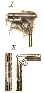
Flat wire straightening
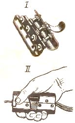
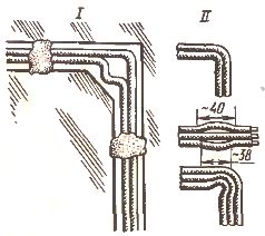
Wind the wires, which are usually supplied in special drums or wound on coils, by twisting them freely on a special device (you should not drop the wires with rings to avoid twisting and bending them). Measure the sections of wires to the required length, place them in the roller press (I) and pass through it several times, i.e. align (II). The wire is also straightened by pulling it through a dry soft cloth held with it in the hand.
Phone processing
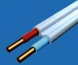
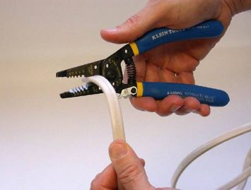
Remove the separation base at the ends of the wires at a distance of 70 — 80 mm with a special tool (for example, MB -2U) so that a part of the wire with a separation base fits into the junction box or the housing of the mounting device at a distance of 5 — 10 mm, and the rest (65 — 75 mm) was without spacer base. The base is also removed with pliers, a knife or scissors without damaging the core insulation. Sections of wires (two-wire I or three-wire II) in the places of their connection must have a margin that guarantees the possibility of reconnection of the cores.
Fastening wires with nails
Attach the wires with nails, gluing, fasteners or special clamps made of plastic or rubber, allowing a distance between the attachment points of no more than 400 mm. To avoid damage to the insulation of the wires, drive nails in two steps: first with a hammer, then with a special mandrel and hammer.
Crossing two wires
Determine where the wires cross before attaching them. Wrap 1 - 2 layers of adhesive light-resistant insulating tape (e.g. polyvinyl chloride) over one of the wires. Fix the wires at a distance of 50 mm from the crossing line.
Making a bend with flat wires
Determine the place of rotation of the wire. Cut the spacer base of the two-core wire at a distance of 60 mm and the three-core wire at a distance of 60 and 40 mm respectively on the wide and narrow spacer bases. Smoothly bend the outer core with a radius of at least five of its diameters. Bend the second core with the same radius in the corner of the semi-contours for the two-wire wire (I), and for the three-wire wire (II) the second and third wires.
Distribution box installation
Select a branch field. Check the accuracy of the marking at the place of its installation. If the box is not attached, but is held on the wires, install it on the wire entry, if it is attached to the foundation of the building, insert the wires into it after full attachment.
Connecting wires inside the box
Connect copper or aluminum wires with screw clamps on the box, or in their absence - by crimping or soldering, followed by insulating the joints with adhesive insulating tape or insulating caps. Carefully place the connection and the insulated ends of the wires in the box so that they do not come into contact with each other.
Design of wire branches
Check the accuracy of the installation of the box according to the marking. Make sure that the ends of the wires are firmly connected, the attachment points of which must be at a distance of 50 mm from the edge of the box.
Installation of hidden electrical wires with flat conductors
Laying and installation of flat wires at temperatures below -15 ° C is prohibited. All wire connections are made by welding, crimping into sleeves or junction box clamps.
Tools and Fixtures - Electrician's Tool Set, Wire Splicing and Punching Tool.
Materials (edit) — flat wires, 3 mm asbestos cardboard, junction boxes, switch mounting boxes, switches and sockets, flexible tubing, insulating caps, adhesive tape, body fasteners, insulating sleeves.
Laying of flat wires on non-flammable bases
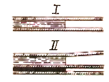
Flat conductors are laid: in furrows with subsequent embedding with gypsum solution (I), directly under a layer of wet plaster without channels (II) or under dry plaster (III). When laying refractory foundations in the furrows, the wires are fixed at regular intervals by "freezing" with alabaster solution and plastered during the finishing works.
Laying flat wires on combustible bases
Flat conductors are laid on combustible bases only after preliminary application of a layer of plaster and lining of sheet asbestos (I) with a thickness of up to 3 mm or pouring of plaster (II). In this case, the asbestos and casting must protrude from each side of the wire at a distance of at least 10 mm.
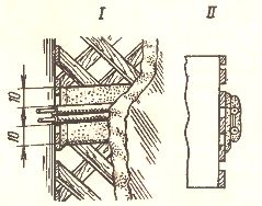
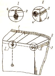
Use of cavities in building structures
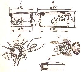
When laying flat conductors in grooves under wet or dry plaster, floor cavities I or other building structures are used. Electrical wiring is installed in several ways. For example, they connect flat wires laid in the groove 2 of the gypsum partition 3 with wires embedded in the front panel 4 or laid in the channels (node Az) and then with wires laid in the floor cavities (node II).
Perform wire twists
When twisting the wires, cut the base between them at a distance of 38 mm and take one core in the corner (I) or bend (II). The wire at the pivot points is fixed by «freezing» with alabaster solution or by other means.
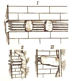
Making connections apartment wires
In hidden laying, the wires are connected in steel junction boxes U197UHL3 070 mm (I) or U198UHL3 with a larger diameter (II), while the boxes are closed with plastic covers. To install the box, a socket is prepared, in which it is embedded ( III) (the openings of the metal boxes through which the wires are inserted must have bushings of insulating materials). After completing the connection in one of the ways, the wires are laid in the box so that the insulated connections do not touch each other (IV), and the box is closed with a lid.
For hidden wiring, plastic boxes U191UHL2 — U195UHL2 (V) are also used, designed for open laying of wires with a cross section of up to 4 mm2. In dry rooms, it is allowed to use nests (niches) and floor cavities as junction boxes. In this case, the walls of the nests should be smooth and covered with lids.
Installation of keys and contacts
Switches, switches and sockets are mounted in special steel boxes U196UHL3 with slots for entering wires. The boxes are built into the prepared sockets. The wires are then connected to the socket, the switch and the switch, which are fixed in the box with remote ears.