Technological cards for installation of electrical equipment
 Technological cards are intended to ensure the correct organization and advanced technology of the installation process when performing work on the installation of individual elements of the electrical unit (switch, disconnector, capacitor, measuring transformer, etc.) or when installing individual units of electrical devices ( switchgear or closed switchgear, power transformer, storage battery, generator leads, solid leads, flexible connections, etc.).
Process maps should be developed for complex work and work done by new methods that are not widely used as part of PPR.
The following sections should be developed in process maps:
1. Technical and economic indicators of assembly works (physical volume of work, labor intensity in man-days, output per worker per day, costs of machine shifts and energy resources).
2.Organization and technology of installation processes (diagram of the organization of work and workplaces indicating the scope of work, the location of parts and pieces of electrical equipment to be installed, the location and procedure for moving machines and mechanisms; basic instructions on the sequence and methods of carrying out work; special safety requirements).
3. Organization and work methods of workers (quantitative and qualification composition of teams, taking into account the achieved and possible over-fulfillment of norms, the work schedule with an indication of the labor intensity per unit of volume and for the entire volume of work).
4. Material and technical resources (list of required assembly materials, list of assembly products and structures produced in assembly product factories and in central assembly and order workshops, list of machines, mechanisms, devices and tools).
5. Calculation of labor costs.
Typical flow diagrams have been developed for the main assembly units of electrical devices and the main types of electrical equipment. These maps can be used in relation to specific local conditions in the development of work production projects and process maps for specific installation sites.
The scheme of sections and the order of arrangement of materials that must be developed when drawing up maps of a particular type may vary depending on the complexity and specificity of the electrical equipment to be installed.
Typical flow diagrams contribute to the introduction of uniform forms of reports, graphs and tables developed as part of specific flow diagrams, and greatly facilitate the work of their preparation, limiting it to the introduction of changes in standard diagrams caused by the specific characteristics of a certain installation location (equipment rigging schemes, the distance of their equipment unloading place to the installation area, presence of mechanisms, etc.).
The following is an example of the development of a technology card for the installation of a rechargeable battery type SK-14.
The map is compiled on the basis of a typical technological map for the installation of storage batteries of the SK-3-SK-20 type, installed at substations with a voltage of up to 500 kV.
Technological card for installing a rechargeable battery type SK-14 for 140 cells.
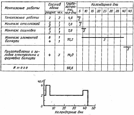
I Technical and economic indicators for installation work
Labor intensity of installation work, taking into account the fulfillment of standards by workers at 130%, man-days — 98.6 V, including: rigging work — 4.8, installation of racks — 1.8, installation of rails — 7.8 , assembly of battery cells — 70, 2, preparation and filling of electrolyte and molding of batteries — 14.0.
Installation time — ~ 40 days. The number of people employed in the assembly of the battery is 2.4. The number of machine shifts of the operation of the crane-2, The number of machine shifts of the operation of the installation SPE-1-2.2
II Basic instructions on the sequence and methods of work.
Construction and finishing works, heating and ventilation systems and lighting must be completed before the start of installation work. A battery forming device must be prepared and tested.
The installation of the battery is carried out in the following sequence:
Preparatory work
1. Acceptance of the battery room for installation according to the act by the construction organization.
2. Acquisition, delivery and installation of mechanisms (installation for ventilation of the battery room, molding device, truck crane), devices and tools.
3. Checking the completeness and delivery of battery equipment, racks and other materials to the installation site.
4. Issuance to the brigade of the order to perform all the work, but the installation of the battery in accordance with the calculation of labor costs.
5. Conduct a safety briefing with the brigade with logbook entry.
Installation of racks
1. Marking places for installation of bearing insulators and racks on them according to the drawings.
2. Inspection of insulators for the absence of chips and cracks and installation of insulators and racks.
3. Secondary painting of racks with acid-resistant paint.
Bus installation
1. Marking the mounting locations of the supporting insulators, shooting the dowels-screws with a PC-52 gun, installing and fixing the insulators on the dowels.
2. Laying tires on support insulators, welding and fixing tires.
3. Wrap the insulators with paper before painting the battery compartment.
4. Cleaning insulators and busbars after painting the room.
5. Double painting of tires with colored acid-resistant enamel and lubrication of tires after painting with technical petroleum jelly.
Installation of glass tanks
1. Unpack the tanks and inspect them for cracks and chips.
2. Wipe the tanks, rinse with distilled water and wipe dry.
3.Assembly according to the pattern of glass insulators on racks and tanks on glass insulators (Fig. 1).
4. Alignment of tanks with level and cable with vinyl plastic pads.
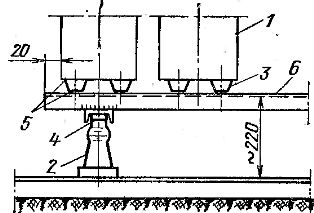
Rice. 1. Installation of storage tanks on metal racks: 1 — glass tank SK -14, insulator OF -6-375, 3 — glass insulator, 4 — bolt M10 x 30 mm, 5 — vinyl plastic spacers, 6 — rack.
Assembling the battery
1. Unpacking boxes with plates, checking and identifying defective plates in accordance with GOST, the arrangement of plates in piles, depending on polarity.
2. Align curved plates and connecting strips.
3. Cleaning the plates with a steel brush.
4. Assembling the battery cells (fig. 2).
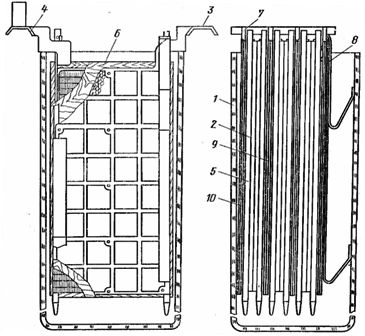
Rice. 2. Assembling the battery cells: 1 — glass vessel, 2 — positive plate, 3 — tape without tip, 4 — tape with tip, 5 — birch rod, 6 — separator, 7 — ebonite pin, 8 — springs, 9 — middle negative plate, 10 — same extreme.
Soldering plates and connecting busbars to batteries
1. Removal of residues from battery plates and connecting strips.
2. Soldering the ends of the plates with the connecting strips with solder adhesives.
3. Checking the quality of soldering and correcting the detected defects.
4. Transfer the patterns to the following tanks and remove excess solder lead particles from the boards, bonding strips, and solder joints.
5. Cleaning the tanks with installed plates from dust and lead particles with a vacuum cleaner.
6. Installation and installation of separators.
7. Welding tires with batteries.
8. Drawing up with the customer a bilateral certificate of readiness of the battery for filling with electrolyte.
Preparation of the electrolyte and its filling in batteries
1.Assembling the scheme for preparing and pouring electrolyte into batteries.
2. Preparation of the electrolyte, bringing it to a density of 1.18 g / cm3 and cooling to + 25-30 ° C.
3. The first charge of electrolyte in the battery tanks to a level 10 mm below the level of the lower edge of the plates.
4. Final charging of the electrolyte to a level 10-15 mm above the upper edge of the plates and closing the battery tanks with lids.
Formation and testing of batteries
1. Turn on the ventilation system.
2. Assembling and checking the battery shaping circuit.
3. Formation of the storage battery.
When carrying out all types of battery installation work, pay special attention to compliance with all general and special occupational safety and protection measures provided for by the current safety regulations, as well as the "Instructions and care rules for stationary batteries from batteries with surface plates «and a typical technological card for mounting rechargeable batteries of types SK-3-SK-20.
III Installation schedule for a 140-cell SK-14 rechargeable battery
Battery installation and work schedules are based on an average worker compliance rate of 130%, except for battery filling and molding, which are done on time.
IV Material and technical resources
List of main and auxiliary materials
Metal racks — 1 distilled acid — 120 l., distilled water — 2940 l., lead for soldering plates — 450 g, solder POS -30 — 40 g.hydrogen — 120 l., liquid propane-butane — 80 g., oxygen — 120 l., technical petroleum jelly — 20 g., acid-resistant enamel paint red, blue and white — 30 g., the same but gray — 140 g., purified soda for neutralizing solution — 15 g, wrapping paper — 100 g, brass tire welding wire — 10 g, borax — 8 g, cleaning material — 150 g, rosin — 8 g.
List of machinery, mechanisms, tools, devices, inventory and overalls
Vinyl plastic containers for electrolyte - 1 set, pump for pumping electrolyte - 1 set, vacuum cleaner for cleaning tanks from dust - 1 set, work table with a vise - 1 set, LPG cylinder with a capacity of 5 l - 3 pcs. , Oxygen cylinder — 2 pieces, welding transformer — 1 piece, welding device set — 1 piece, acid-proof rubber hose — 45 m, 220 / 12V transformer and portable lamp — 1 set, PC-52 gun — 1 set, hydrogen cylinder — 1 Piece, Discharge Resistor, — 1 Set, Kit of Battery Mounting Tools, Fixtures, and Coveralls (found under the Battery Master's Report).
V Calculation of labor costs
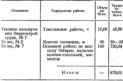
The labor of preparing and filling the battery tanks with electrolyte and all battery forming operations are paid according to actual labor costs on a time basis. These labor costs are not included in the cost estimate.