Cable terminals
 Final sealing is carried out to seal the cable in the immediate vicinity of the connection point of its current-carrying wires to devices, busbars of distribution devices and other elements of the electrical installation.
Currently, the following types of cable breaks are used for voltages up to 10 kV: in a steel funnel, in a rubber glove, epoxy resin, as well as from polyvinyl chloride strips.
Termination of cables in steel funnels (type designation KVB) is still widely used for electrical installations with a voltage of up to 10 kV located in dry heated and unheated rooms. Such a seal can be of three designs:
-
KVBm — with an oval small funnel without a lid and mounted without porcelain bushings,
-
KBBk — with a round funnel, at the exit of which the cable cores are located on the vertices of an equilateral triangle (at an angle of 120 °),
-
KVBo — with an oval funnel, at the exit of which the conductors of the cable are located in one row.
Gaskets KVBo and KVBk are used to connect cables designed for voltage up to 10 kV with conductors of arbitrary cross-section, when terminating cables for voltage 3, 6 and 10 kV, the funnel is installed with a cover and porcelain bushings, and when connecting cables for voltage up to 1 kV — without cover and bushings.
Sealing the ends of the cables in a steel funnel is used most often, since the materials necessary for the manufacture and casting of funnels are always available in any electrical equipment. For the termination of three-core cables for voltage up to 1 kV with a cross-section of up to 3 x 120 mm2 and four-core cables with a cross-section of up to 4 x 95 mm2, mostly oval steel funnels of small size KVBm are used. Sealing is done in the following order.
The steel funnel to be installed is cleaned of dirt, placed on the cable (Fig. 1, a) and slid along it (after wrapping it with paper to protect the funnel from contamination). After cutting the end of the cable, heat the mass of the MP-1 brand to 120 ... 130 ° C and carefully scald the cut section.
The veins are isolated with an adhesive tape of polyvinyl chloride (Fig. 1, b), applying half-overlapping turns. The funnel is pushed onto the cut end of the cable (Fig. 1, c), the wires are located in it. Then, after marking the location of the funnel neck on the cable, it is moved again.
Also, attaching the ground wire to the sheath and armor of the cable with a wire bandage, solder it (Fig. 1, d ... f).After removing the remaining ring tape over the insulation and then on the cable armor (in the place where the funnel neck should be), several layers of resin tape are wound conically (Fig. 1, g) for a tighter nozzle on the funnel neck.
A ground wire passes through the middle of the winding (after 3 ... 4 layers). The funnel is pressed into place, with effort it is placed on the reel and fixed vertically to the structure with clamps, to which the ground wire is then attached (Fig. 1, h).
The ears are soldered or welded to the ends of the cable cores, the cable cores are bent so that they are at the same distance from each other and from the walls of the funnel, and then, heating the funnel to 35 ... 50 ° C, fill it with hot cable table. While cooling and shrinking, the cable mass is poured into the funnel so that its final level is no more than 10 mm below the edge of the funnel.
For corrosion protection, the funnel, bracket and supporting structure are painted with enamel paint. The funnel is marked showing the number and cross-section of the cable on it.
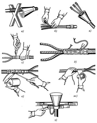
Rice. 1.Sequence of operations (a … h) finishing the cable in a steel funnel
Termination of cables in rubber gloves (type designation KVR) is allowed in rooms with a normal environment with a difference in the levels of the location of the ends of the cables no more than 10 m and is used for three-core cables designed for a voltage of up to 1 kV, with a transverse conductor cross-section up to 240 mm2 and four-core cables with conductor cross-section up to 185 mm2. The rubber gloves are made of nitrite rubber PL-118-11.
After cutting the end of the cable, the installation of the KVR termination (Fig. 2) is carried out in the following order.First, on the cut cores 4 of the cable, several layers of winding 2 made of adhesive polyvinyl chloride tape are applied at a distance to fix the paper insulation and round its sharp edges to facilitate their passage through the pipes 3 and branches (fingers) 14 on the glove.
The body (body) 75 of the glove is bent with pliers in several steps along the entire circumference in an area approximately equal to the width of the clamp 6 (25 ... 30 mm, depending on the size of the glove).
The section of the cable sheath 9 between the two annular cuts is removed and a bandage 13 of heavy thread is applied to the exposed part of the insulation of the cross 12, after which a roughness is created on the bent part of the glove body 15, for which by wiping it with rag soaked in gasoline, it is processed with a cardo tape file or brush. The part of the shell on which the glove will be glued is cleaned to a shine and then wiped with a cloth soaked in gasoline.
The bent portion of the glove body and the shell section are then coated with a thin layer of No. 88H glue. If the diameter of the shell is smaller than the inner diameter of the glove, an oil-resistant rubber band is wound around the shell, each layer of which is also coated with adhesive. After the 5 ... 7 minutes required for the glue to dry, the body of the glove is folded over a roll of tape. The depth of attachment of the glove to the housing E should be 30 … 35 mm.
Fasten the body of the glove to the body with a special clamp or two bandages of four turns of copper or mild galvanized steel wire with a diameter of 1 mm (having previously wound two layers of rubber tape on the body in the places where they are installed).
After temporarily tying the rubber tubes with cotton or rubber tape directly in the glove to protect the paper tape insulation from damage, the cores of the cable are bent and bent.
Bend the ends of the wires insulating the wires in an area equal to the length of the pipe part of the tip 1 plus 8 mm, thus preparing the wires of the cable for termination. To facilitate the bending of the pipes, the outer surfaces of these areas are smeared with petroleum jelly or lubricating oil.
Press, weld or solder the tips to the ends of the conductive cores and then wipe their cylindrical (tubular) part with a rag moistened with gasoline.
The curved part of the pipe is roughened with a broom file or a steel brush after wiping it with a cloth moistened with gasoline, and then a thin layer of No. 88H glue is applied to it.
Rolls wound with oil-resistant rubber tape and coated with glue No. 88H are placed in the tip holes formed during pressing by the local indentation method. If the diameter of the cylindrical part of the tip is smaller than the inner diameter of the pipe, that is, there is a difference between them, so many layers of oil-resistant rubber, previously wiped with gasoline and coated with glue No. 88H, are wound on the tip, if it is necessary to eliminate it completely. To seal, the tube is unscrewed onto the cylindrical part of the tip.
Sealing may also be effected by gluing a piece of pipe of such length as to completely cover the cylindrical part of the tip and enter the main pipe at a distance equal to two of its diameters. In this case, the glued surfaces of the pipes (main and section) are first roughened, wiped with rags soaked in gasoline, covered with glue No. 88H and allowed to dry. Then a thick layer of glue No. 88H is applied again to the inner surface of the tube segment and immediately pressed onto the tip.
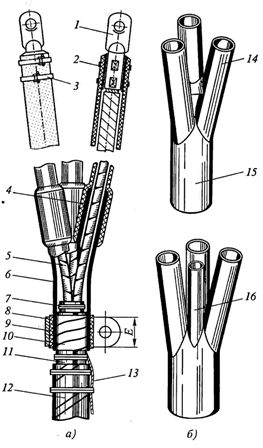
Rice. 2. Construction of KVR termination (a) and type of rubber gloves for three-core and four-core cables (b): 1 — top, 2, 11 — PVC tape winding, 3 — nitrite rubber tube, 4 — cable core, 5 — glove, 6 — bracket, 7 — ground wire, 8 — bumper, 9 — cable sheath, 10 — oil-resistant rubber strip seal, 12 — belt insulation, 13 — bandage, 14 — glove finger, 15 — glove body , 16 — rise for the four-core four-core cable
When completing the core by welding with the help of castings of the LA brand, a strip of oil-resistant rubber is wound over the bare part of the core with the transition of its turns to the tip and insulation of the core. It is also allowed to seal this coil with a continuous bandage of twisted twine with a diameter of 1.5 ... 2 mm, which is then covered with asphalt varnish.
The most common methods of sealing rubber tubing to fittings are shown in Fig. 3. Rubber tubes 1 are fixed on the tip body with a special tape 3 or four turns of copper wire with a diameter of 1 mm.
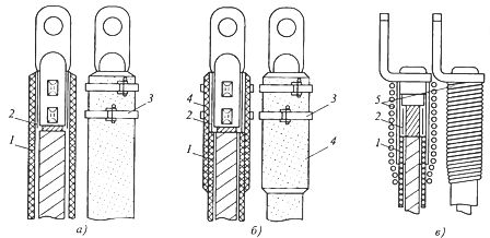
Rice. 3.Methods of sealing rubber pipes on an aluminum tip: a — by pre-rolling the pipe, b — using a piece of pipe, c — twisted twine on a molded tip, 1 — rubber pipe, 2 — coil with oil-resistant rubber tape, 3, 5 — bandages of steel tape and twine, 4 — connectors made of rubber tube
Epoxy cable termination, it is distinguished by simplicity of execution, reliability, high electrical and mechanical strength, safety and heat resistance (the working temperature of such a seal is from -50 to +90 ° C).
It has a general designation of type KVE and is used to terminate power cables designed for voltages up to 10 kV and used in any premises, as well as in outdoor electrical installations subject to protection from direct exposure to atmospheric precipitation and sunlight.
An epoxy finished body is formed after curing of the epoxy compound, molded into a conical shape, temporarily slid along the end of the cable.
The epoxy body insert (Fig. 4) can be of the following design:
-
KVEN — with nitrite rubber tubes of wires for use in dry rooms,
-
KVED — with two-layer (lower layer of polyvinyl chloride, upper layer of polyethylene) pipes on the veins for use in humid rooms and areas with tropical and subtropical climates,
-
KVEP — with an exit from the casing of insulated conductors soldered inside multi-core conductors of a cable designed for voltage up to 1 kV, for use in humid rooms and areas with tropical and subtropical climates,
-
KVEz — with nitrite rubber tubes on single-wire conductors of cables designed for voltages up to 1 kV and the "locks" device inside the box for use in humid rooms and areas with tropical and subtropical climates.
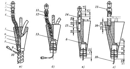
Rice. 4. Final epoxy sealing of cables of different designs: a — KVEN, b — KVED, c — KVEP, d — KVEz, 1 — tip, 2 — bandage or clamp, 3 — nitrite rubber tube, 4 — conductive wire in factory insulation , 5 — case of epoxy mixture, 6 — bandage made of raw threads on the insulation of the belt, 7 — cable sheath, 8 — double-layer winding, 9 — wire bandage of the grounding wire, 10 — grounding wire, 11 — winding of cotton tape , covered with an epoxy mixture, 12 — double-layer pipe, 13 — insulated wire, 14 — the junction of the core by soldering, 15 — winding from adhesive PVC tape, 16 — bare part of the core
In addition to the above, KVEo terminals are also used without an epoxy cast body, but with a reel of cotton tapes glued with an epoxy mixture, they are intended for the final termination of single-core cables intended for voltages up to 1 kV, under the same conditions as KVEN terminals and KVED.
The installation of the terminals begins after cutting the cable, carried out in accordance with the general instructions. The dimensions of the cable strips for the terminals KVEP and KVEz are determined using fig. 5 and tab. 1.
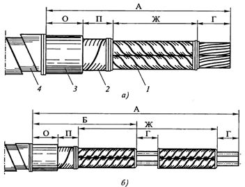
Rice. 5. Cutting the cable for fitting KVEP (a) and KVEz (b): 1 — core in factory insulation, 2 — belt insulation, 3 — sheath, 4 — cable shield
The peculiarity of the KVEP termination is that it is not the conductive cores of the cable that come out of it, but the pieces of insulated wire attached to them. It is performed as follows.A piece of insulated wire of the required length with a cross-section corresponding to the cross-section of the cable core is selected, its ends are cleaned, preparing to connect one of them to the cable core and the other to the tip.
Table 1 Sizes of cable bands for fitting KVEP and KVEz fittings
Size of the segments of the segments of the channels, mm (see Fig. 5) AOONSGBCEP-1, Quep-2170352040-Qvep-3, Queep-4210502045-CVEP-5, Quep-62405020-Quep-724-CV -2, KVEz-3F + 5535202595KVEz-4, KVEz-5F + 55352025120
Notes:
1. The length of the cut cable cores (segment Ж) is taken depending on the conditions of laying and connection, but not less than 150 mm.
2. Section G for termination of KVEz is determined depending on the method of termination of the wires.
The bare ends of the copper core of the cable and the copper wire are degreased, inserted into a connecting copper sleeve and soldered by pouring POS-30 or POS-40 solder into it. The aluminum core of the cable is connected to an aluminum wire in an aluminum sleeve by soldering, pouring or crimping.
After connecting the core of the cable to the conductor, a spool of adhesive polyvinyl chloride tape is applied to the exposed area, the ground conductor is soldered to the shield and strips, and then the core and sheath at the termination point are degreased with acetone until they provide better adhesion to the epoxy compound.
A movable cone is mounted on the prepared end of the cable, so that the cores of the cable are at a distance of at least 6 ... 7 mm from each point of its edge, and the soldering section is inside. The mold is poured with an epoxy mixture and after hardening it is removed.
KVEz epoxy termination (see Fig. 4, d) differs from KBEp termination in that 25 mm long sections G, called locks, free of insulation are left on the single-core solid wires of the cable (see Fig. 5). A tube made of nitrite rubber of this length is placed over the wires with exposed sections, which will allow one end to be pulled over the cylindrical part of the tip and the other to sink the recesses in the epoxy body to a depth of at least 20 mm.
When installing and filling the mold with epoxy, KVEz embeds meet the same requirements as KVEP embeds.
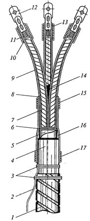
Rice. 6. Termination KVV: 1 — cable shield, 2 — ground wire, 3 — wire strips of shield and sheath, 4 — cable sheath, 5 — factory-made insulation, 6 — cotton yarn bandage on waist insulation, 7 — core in factory insulation, 8 — glass-shaped belt winding, 9 — core winding, 10 — cotton yarn bandage on core insulation, 11 — bare part of the core, 12 — cable clamp, 13, 15, 17 — bandages, 14 — filling, 16 — leveling roller
Termination of cables with PVC strips
End seals made of polyvinyl chloride tapes and varnishes (type designation KVV) are used for cables insulated with paper, intended for voltages up to 10 kV and used indoors, as well as in outdoor installations at an ambient temperature not exceeding 40 ° C and subject to protection from direct exposure to precipitation and sunlight.
KVV termination is used when the difference in levels of the highest and lowest point of the location of the cable along the route is no more than 10 m, otherwise a special KVV termination is used. The installation of KVV fittings is carried out at an ambient temperature of at least 5 ° C.
Sealing of the KVV (Fig. 6) is carried out with adhesive (first version) or non-adhesive (second version) with polyvinyl chloride tape using compositions No. 1 (lid) or No. 2 (filling), respectively, PVC glue (Fig. with an adhesive layer ) the tape is 0.2 ... 0.3 mm thick and 15 ... 20 mm wide, and the non-sticky tape is 0.4 mm thick and 25 mm wide. The dimensions of the cable cross-section for completing the KVV are determined using a table. 2 and fig. 5, a.
Cable lugs are welded, soldered or crimped to the ends of the cable cores.
When terminating the cable cores by crimping the lug through a local recess, only tube lugs that have a factory seal are used. Before crimping the aluminum wire of the cable, the inner surface of the tip is cleaned with a steel wire brush and lubricated with quartz-vaseline paste.
After removing the insulation from the ends of the wire to a length equal to the length of the pipe part of the tip and rubbing them from the cardo tape to a metallic shine, the exposed area is also lubricated with quartz-vaseline paste.
After such preparation, the tip is placed until it rests on the core, and after placing it in the pressing mechanism with a previously selected punch and die, bend it.The pits obtained on the tubular part of the tip after crimping are wiped with a cloth moistened with gasoline, lubricated with composition No. 2, and then filled with rolls of polyvinyl chloride tape and polyvinyl chloride composition No. 2.
The volume and shape of the tape roll must correspond to the depth and shape of the opening. The hank is pressed into the hole and then coated with compound #2.
The ledges formed at the transitions from the outer surface of the cylindrical part of the cable lugs to the core insulation are leveled with a coil of polyvinyl chloride tape 7.5 mm wide, for which the tape roll 15 mm wide is cut in half. Similarly, align the skirting at the transition from the lead or aluminum sheath to the belt insulation.
Table 2. Cable strip dimensions for KVV terminal installation
Size of the installation Conductor section, mm2, for voltage cables, kVDimensions of channel segments, mm (see Fig. 4, a)1610АОНСКВВ-1До 25—F + 653015KVV-235…5010…25-F + 705020KVV-370…9535 …5016…25F + 1058025KVV-4120… 15070…9535… 70F + 1058025KVV-5185120…15095…120F + 12510025KVV-6240185150F + 12510025KVV-7-240185F + 12 510025KVV-8—240F + 12510025
Notes:
1. The length of the cut wires (segment G) is taken depending on the connection conditions, but not less than 150 mm for a cable for a voltage of 1 kV, 250 mm for a voltage of 6 kV and 400 mm for a voltage of 10 kV.
2. Section G is determined depending on the method of termination of the wires.
Then wipe the outer surfaces of the wire insulation and the belt insulation with a rag slightly moistened with gasoline, and each core from the belt insulation to the contact part of the tip is wound with polyvinyl chloride tape (in three layers with a wire cross-section of up to 95 mm2 and in four layers with a cross-section of 120 mm2 and more).
The layers of polyvinyl chloride tape are applied with a 50% overlap of the previous turn (overlap) and with a tension in which the tape is stretched with a reduction of the initial width by no more than 1/4. The final winding layer of each core is performed by approaching the entire pitch of the lead or aluminum sheath.
The winding of each core is covered with a brush with a thick layer of composition No. 2 in sections 70, 100 or 120 mm long (counting from the end of the belt insulation) with cable diameters along the sheath, respectively, up to 25, 40 and 55 mm. The composition is applied to that part of the surface of each core which faces inwards.
Using a brush or wooden spatula, compound No. 2 is used to fill the internal space between the veins. Then the veins are pressed with hands into a bundle and fixed in this position with a cotton tape bandage at a distance of 10 mm from the area covered with composition No. 2.
The outer surface of the bundle of compressed veins is also coated with a thick layer of composition #2 (using the composition extruded in the bundle). The amount of composition in the grooves formed by the veins should be such that it comes out in the form of three rolls above the surface of the bundle, that is, they should not be left unfilled with the composition, in which air and moisture can accumulate.
On the section of the cores compressed into a bundle and on the section of the cable jacket, a strip glass winding of eight layers of polyvinyl chloride tape is applied with 50% overlap (regardless of the cable cross-section and voltage) and at a distance of 20 mm from the ends of this winding and on the cylindrical part of a cable rod — twisted bandages of twine with a diameter of 1 mm (Table 3).
Dressings are covered with polyvinyl chloride compound No. 1 using a brush.
To increase moisture resistance, the outer surface of the seal is covered with asphalt varnish or colored enamel paint.
A temporary bandage made of cotton tape applied 10 mm above the glass coil can be removed after bending the wires and connecting them to the contacts of the corresponding rubbers of the apparatus or switchgear, and after sufficient drying of the No. 2 composition.
In addition, before the composition 2 dries, it is desirable to release the embedment from the pressure of the impregnating composition, which arises due to the difference in the levels of the location of the ends of the cable. The connection of the cable with the newly installed termination under load is allowed no earlier than 48 hours after the end of the installation.
KVV seals using non-adhesive polyvinyl chloride tape and liquid compound #1 are installed in the same manner as seals using adhesive tape. In this case, each layer of coil (to avoid weakening the density of its overlay before the completion of the next layer) is temporarily fixed with a bandage of 2-3 strands of raw threads.
Table 3 Dependence of the width of the bandage on the cross-section of the cable cores
Core section, mm2162535507095120150185240 Bandage width, mm25303540455055657075
The surface of each layer of the coil is first covered with one, and after drying - with the second layer of composition No. 1. The next layer of tape is applied to the third layer of composition No. 1, which is not applied immediately along the entire length, but gradually in sections with a length of 100 mm.
KVV seals of a special design are used with large differences in the location levels of the cable ends. They differ from the seals of the first and second designs in that the winding on the core insulation is made of five layers of polyvinyl chloride tape, and the sealing spine is sealed with an epoxy compound instead of No. 2 polyvinyl chloride compound.
In special construction KVV fittings, the leveling coil between the tip and the core insulation is made with cotton tape with a generous coating of epoxy on each turn.