Connectors for power cables: requirements, classification, types, installation, common mistakes
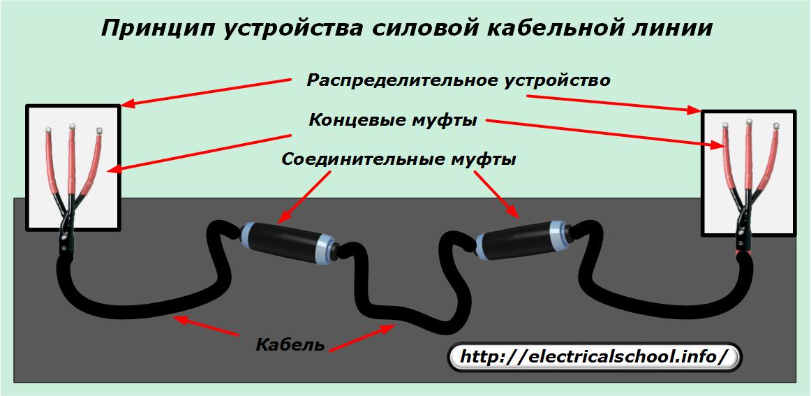
The characteristic of the design of any power cable line in electrical networks is the need to implement them in a sealed housing, protected from the harmful effects of the cable on the environment. The sheath of a cable buried in a trench is constantly exposed to the influence of groundwater, dissolved soil acids and mechanical stress.
The length of cable lines can reach several tens of kilometers, and manufacturers are forced to produce them with a strictly measured construction length, which is limited by the size of the cable roll and the possibilities of its transportation by vehicles.
Therefore, when installing such power lines, there is a need for high-quality connection of building sections of cables in one line and their connection to the input devices of electrical equipment.
For this, connectors are used, which are called:
1. connection for connecting cable sections to each other;
2.a terminal making the switching of the terminal sections of the cable line to the distribution busbars of the inputs of the electrical installation panel.
In this case, the first structures are completely located in the trench and covered with earth, and the second ones are protected by the metal body of the shield, closed with a lock, from the penetration of unauthorized persons.
Technical requirements for connectors
If you look at the picture above, you can clearly see that all the connectors connect in series in separate parts of the cable line. This imposes on them the need to transmit electricity, similar to the cable, with minimal voltage losses and retaining all its electrical characteristics.
In this case, the area created by the contact surface of the wires with the sleeve should correspond to their dimensions or even slightly exceed them, and the crimping force should provide not only mechanical strength, but also a high-quality flow of electric current with as much as possible - the low transfer resistance.
Therefore, the wires of all power cables are attached:
-
ears that are tightened with bolts;
-
bolts or crimp sleeves.
The insulation layer of the connector, like the cable itself, must:
-
withstands the phase-phase voltage of the electrical installation;
-
excludes case breakdown;
-
to withstand the aggressive impact of the soil for decades.
Classification of connectors
The choice of connector design is influenced by such characteristics of the cable as:
-
voltage value;
-
number of residents;
-
cross-section and material of the wires;
-
type of interphase insulation;
-
methods of protection from external mechanical and chemical influences.
To meet these conditions, sleeves are created for specific cables.
According to the value of the operating voltage, connectors are produced for:
-
high voltage cable lines;
-
electrical installations up to 1000 volts.
The number of cores connected by connectors, as a rule, can be limited to three or four. But in some cases there are cables with different number of cores.
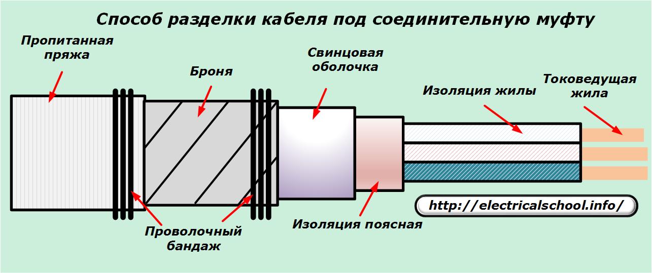
To install the sleeve on the cable, it is necessary to properly cut the ends, carefully remove the layers of insulation and sequentially prepare each surface for installation in the sleeve, as shown in the photo below.
The principle of connecting a wire with bolts for two cables is shown in the photo.
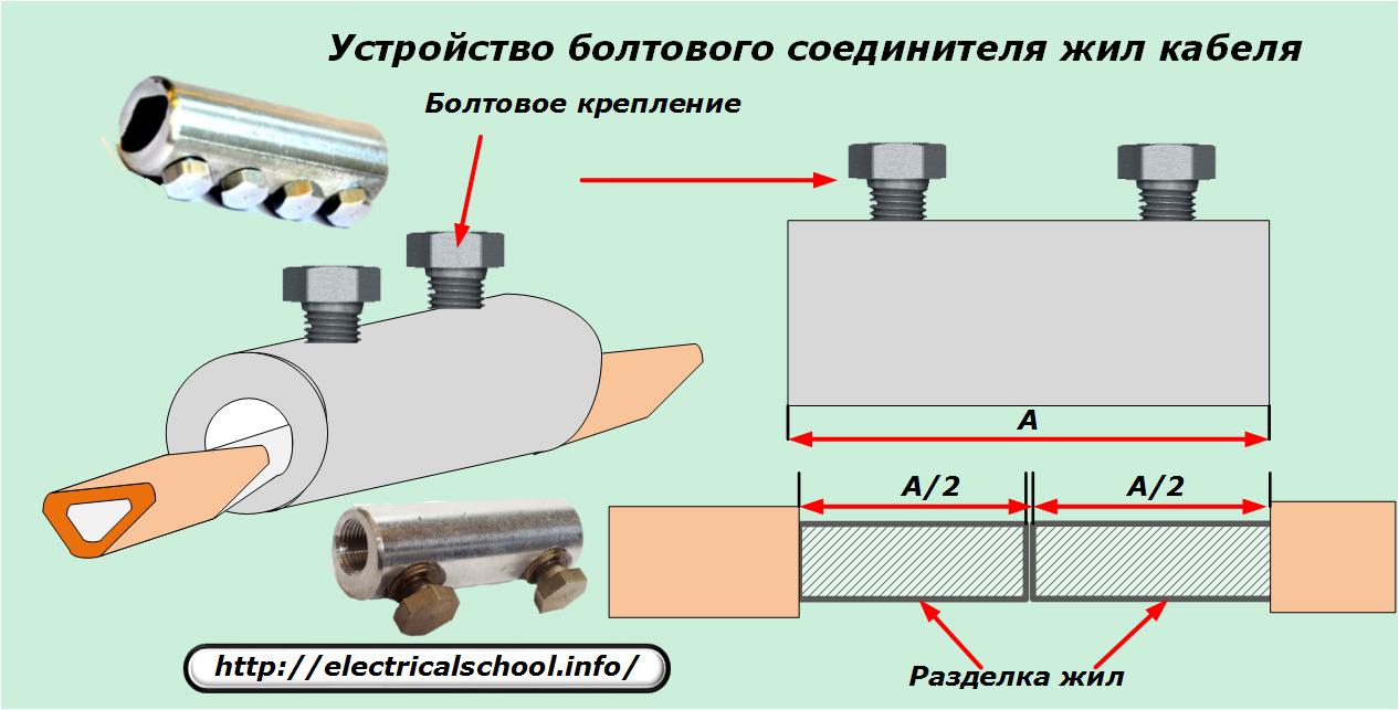
The insulation from each core is stripped for half the length of the connecting pipe, into which both ends are inserted and crimped with bolts.
In the same way, the cut wire is connected to the end terminal.
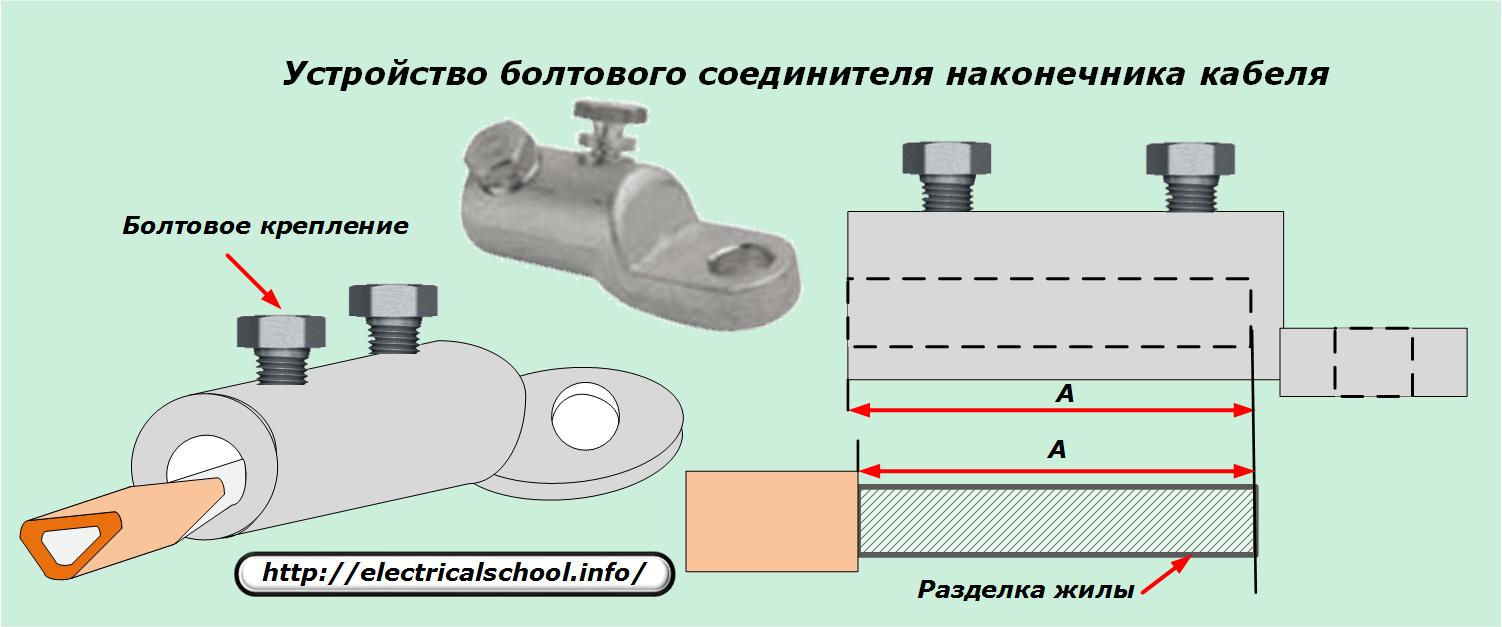
Only then is the insulation removed along the entire length of the pipe recess.
For multi-core copper wires woven into one bundle, it is convenient to use special ears made of deformable soft metals, which, when compressed with a special crimping tool, create a strong mechanical connection and good electrical contact.
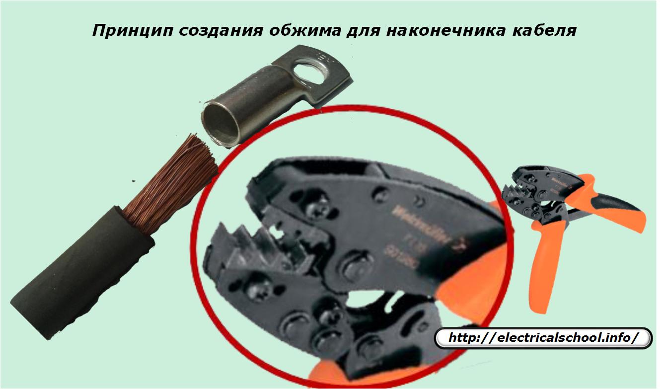
The force of evenly distributed crimping reaches several tons.
The type of phase-to-phase cable insulation determines the design of the applied connectors.
Connectors
For example, the 1Stp-3×150-240 S model designed for assembling cores wrapped in a special class of paper with an impregnating layer. Decoding its designation:
-
«1» — for voltages up to 1 kV;
-
«C» — connection;
-
«TP» - heat shrinkable (thermoplastic);
-
«3» — the number of veins;
-
«150-240» - the limits of the cross-section of the wires used in mm;
-
«C» — with delivery of a mechanical bolt coupling.
Connectors for cables with PVC or XLPE conductors in the designation have an additional index «P», for example, 1PStp-4×150-240 S.
In this case, after the designation of insulation thermoplasticity, a design feature can be indicated: «R», «B», «O», which means: repair, with armor, single-core cable. Examples of designations:
-
StpR, PStpR;
-
StpB, PStpB;
-
StpO, PStpO.
Reducing couplings
They are used as a type of connecting structures that allow you to connect the ends of different types of cables. An example of this is a connection 1Stp-PStp-3×150-240 S.
End connectors
For cable lugs with impregnated paper insulation, the designation 1KV (N) TP-3×150-240 N is used... Here additional symbols K, B, H, H carry the following information:
-
terminal;
-
internal (external) installation;
-
with a set of mechanical bolts.
For the marking of bushings of cables with PVC or XLPE insulation, the rules listed above with the designation of the symbol «K» apply.
In terms of external protection design, the cables covered with armored tape are the most durable. To connect their ends, as already noted, connectors marked with the index «B» were created. Simple sheaths of power cables have no armor.
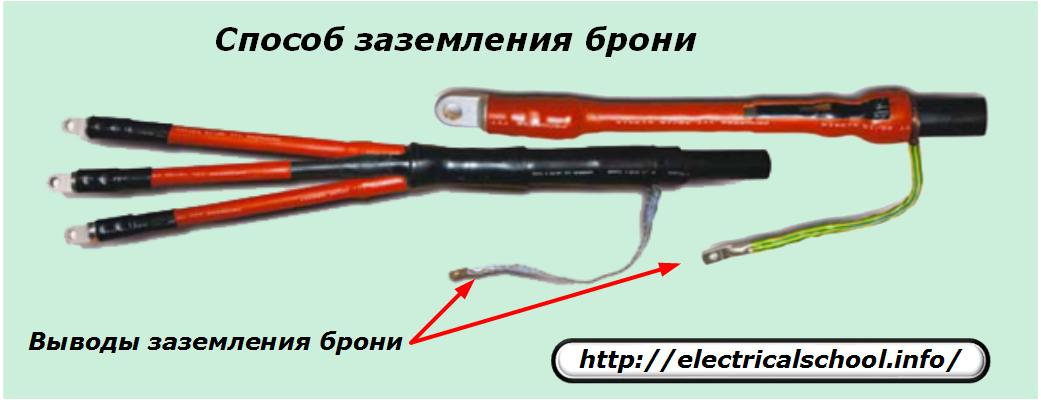
The protective shield must have the same potential with respect to earth and veins. For this purpose, all ends of the grounding cable are connected to the metal parts of the connectors in a certain way through the corresponding terminal.
To connect high-voltage cables with a voltage of 6-10 kV, connectors are used:
1. epoxy resin:
2. lead.
Epoxy constructions most resistant to the impact of an aggressive environment. They are also used as retainers for paper-impregnated cable insulation. For their installation, a case is made of two halves, in which the electrical connections are installed. The set of such a clutch includes:
-
container with mixed resin and filler;
-
ampoule with hardener;
-
auxiliary materials.
Epoxy connectors are additionally wrapped with sheet asbestos and protected from possible mechanical damage by metal casings with a wall of at least 5 mm.
Lead connectors designed for connecting cables with an aluminum or lead sheath. They are made in the form of pipes with a diameter of 6-11 cm and a length of 45-65 cm. After connecting the metal wires in the usual way, the places with exposed insulation are treated with a hot cable mass of the MP-1 brand to remove moisture. The factory insulation layer is then restored by winding cable paper with oil.
Lead connectors are also protected with metal sheaths, just like epoxy constructions.
Stop clutches are a type of clutch. They are used to prevent the impregnating mass of the paper insulation from dripping on the metal wires when the difference in height is exceeded.
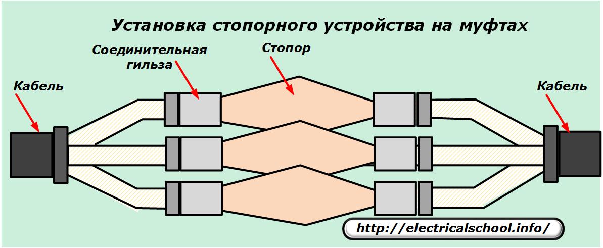
The plug is created from hollowed copper or aluminum rods that are insulated with a layer of several wraps of bakelized paper. Three combination plugs are mounted in a fiberglass or getinax baffle with a brass holder and placed in the middle of the coupling body.
Heat shrinkable sleeves
The installation of an insulating layer based on heat-shrinkable materials made of vulcanizable polymers greatly facilitates the technology of connecting cable cores and speeds up the working time by about half.
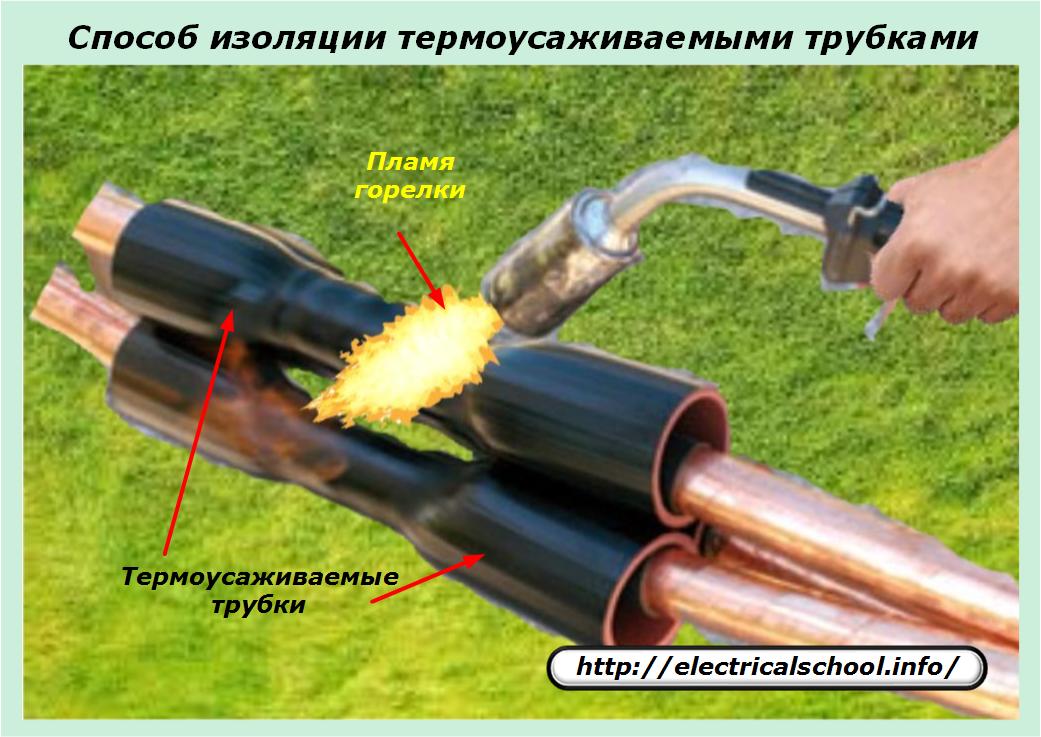
The material of these tubes, when heated to 120-140 degrees by the flame of a burner or industrial hair dryer, shrinks in diameter and fits tightly to the surface to be crimped, sealing it hermetically. Air from all cavities is displaced by heated polymer that penetrates the internal cavities and bumps.
When the polymer cools, it fully adheres to the cable elements and seals them. The service life of such coatings in various environments is at least 30 years.
Cold shrink insulated connectors
These designs use a new elastomer technology based on stretching a layer of dielectric made of special silicone rubber over the insulated surface of the cable. This is done at room temperature and without heating by stretching or cold shrinking.
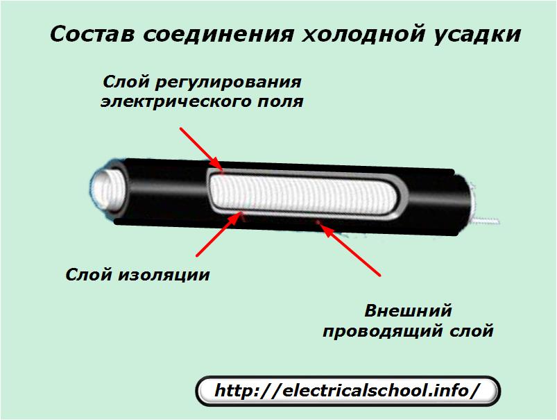
In this method, a cable fitting with an elastomeric material is placed inside the spiral cable and inserted into the installation location. The pipe is then distributed over the connecting surface of the parts and slides into the insulation zone of the spliced elements on both sides.
The spiral layer is then simply unscrewed by turning counterclockwise and removed, and the insulation automatically seals all surfaces hermetically.
This method allows safe installation of connectors in flammable structures.
Typical errors in the installation of end connectors
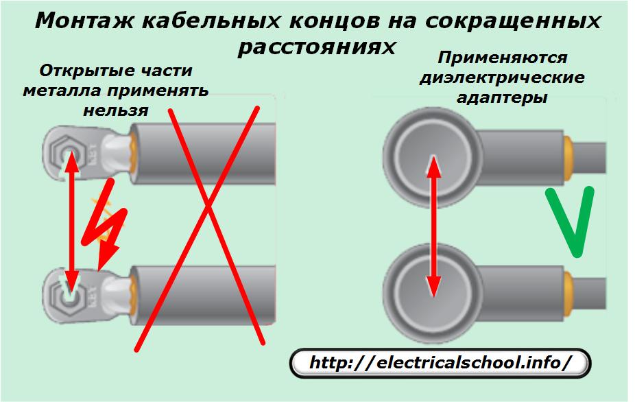
Failure to maintain safe distances
In the end bushings of high-voltage cables, it is necessary to maintain the permissible distances between the phases and the ground, otherwise it is possible to destroy the insulation just inside the switchgear. If the dimensions of the shield do not allow it to withstand this, then special dielectric adapters are used.
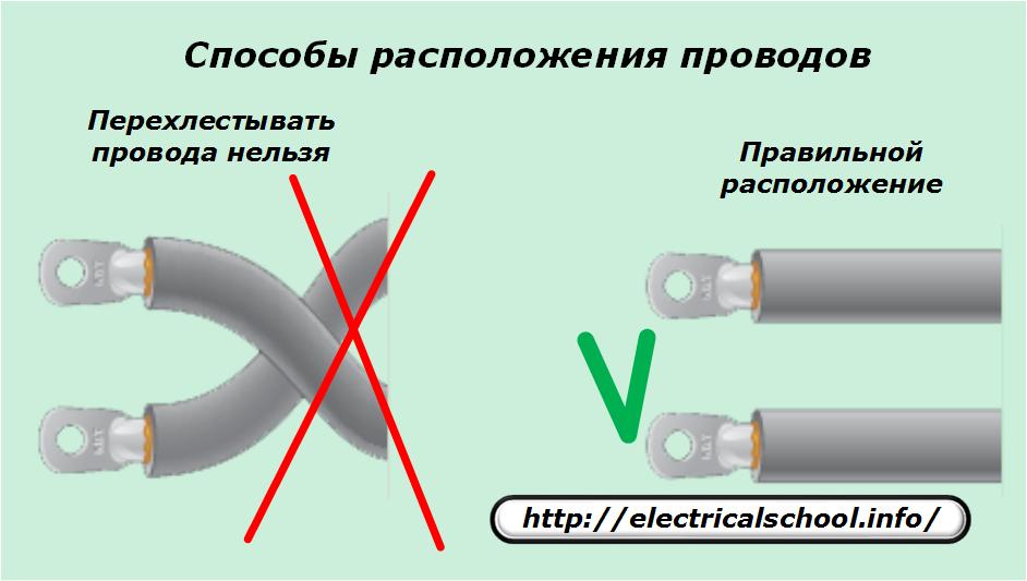
Cross phase orientation
It is impossible to overlap and overlap wires in connectors at a voltage of 6-35 kV due to the appearance of an electric field voltage. If no compensating tube is used to equalize the voltage, then it is forbidden to cross the phases during rephasing.
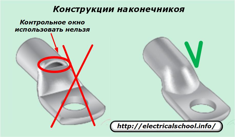
Hints with inspection window
It is forbidden to use ears made with a hole for monitoring the condition of the wire outside the premises in the distribution boards. Through this place, contact with air moisture will occur, which breaks the sealing of the connection, activates the oxidation processes of the metal and deteriorates its electrical characteristics.
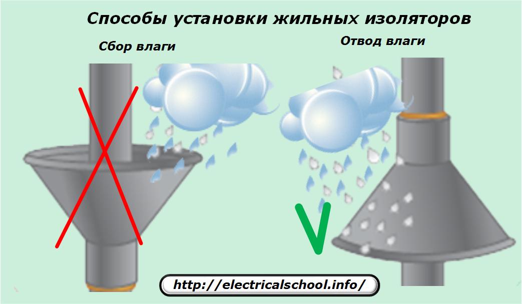
Installation of insulators on the wires of external connectors
The tip can be mounted in a vertical position in a variety of ways, but its protective funnel should always lead moisture away from the connector, not collect and direct it inward.
Also, these insulators must not be allowed to come into contact with each other.
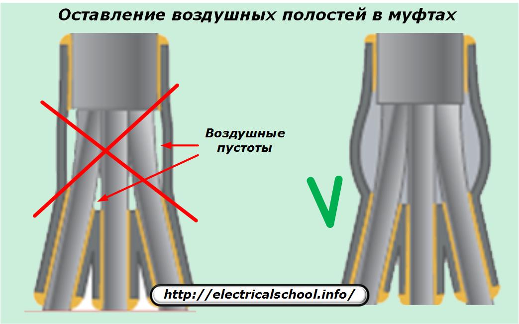
Air cavities in connectors
The presence of air cavities inside the connectors contributes to the development of ionization processes of the gas environment, which leads to damage to the connector material. For this reason, all cavities must be filled with a special sealant.
Typical mistakes when installing connectors
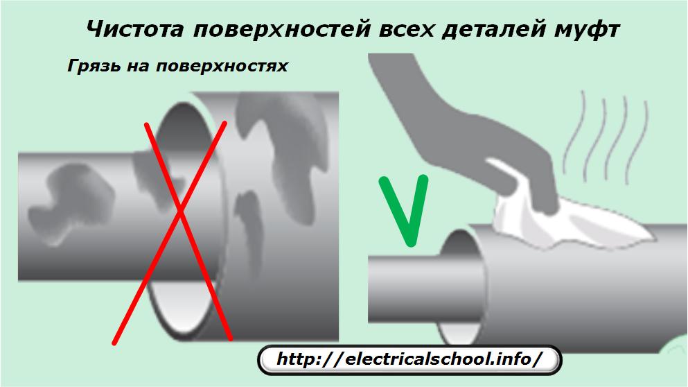
Contamination of surfaces
The installation of connectors on cables is carried out outdoors inside the trenches or repair pits, where it is difficult to organize the cleanliness of the workplace. But when assembling all the elements of the clutch, it is necessary to use plastic films and bags, to monitor the absence of contamination and to quickly clean all surfaces.
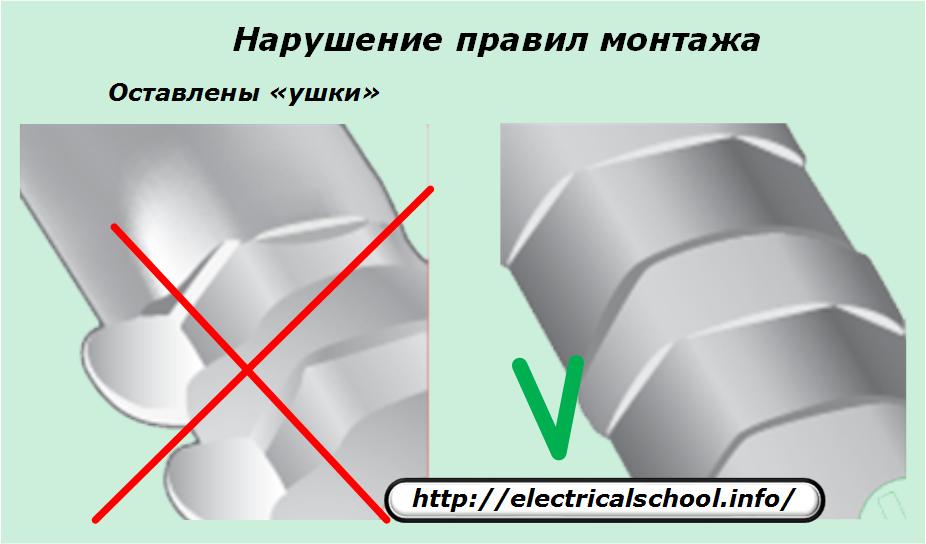
Violation of connector installation technology
The dimensions of the bushings and the cord must comply with the manufacturer's recommendations. Otherwise, scratches, ears, bumps may form. Their appearance should be noticed and immediately smoothed with small files, followed by sanding of the treated surfaces.
The protruding edges of the bolt are also ground. All metal shavings must be promptly removed from insulating surfaces.
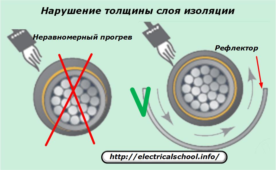
Uneven thickness of cuff insulation
This defect occurs when thick-walled cuffs are shrunk by heat shrink. To exclude it, the heating point must be evenly distributed along the entire perimeter of the parts to be joined. This can be difficult to achieve in confined spaces.
The use of a bent metal reflector made of tin allows uniform heat transfer over the entire surface, which ensures the same melting of the adhesive sub-layer of the pipe seal and its accurate distribution along the circle.
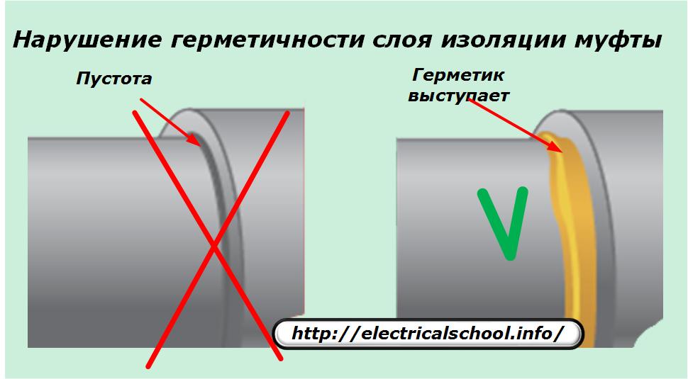
Loss of tightness of connectors
For connectors applied to high voltage cables, 3 tight belts are used:
1. between phases;
2. inside the heat-shrink case;
3. outside the whole structure.
For shrinking external surfaces, an additional coil with sealant is used to seal the joints. After heat treatment, the glue should go beyond the edges of the gap and block access to the interior of the joints from harmful substances.
If the sealant does not protrude, then the technological requirements are not met.
Also, before finally placing the assembled connector in the ground, you should carefully inspect it to identify possible cuts and microcracks on the housing. If they are found, then it is necessary to additionally install a repair collar with an adhesive backing on the body.
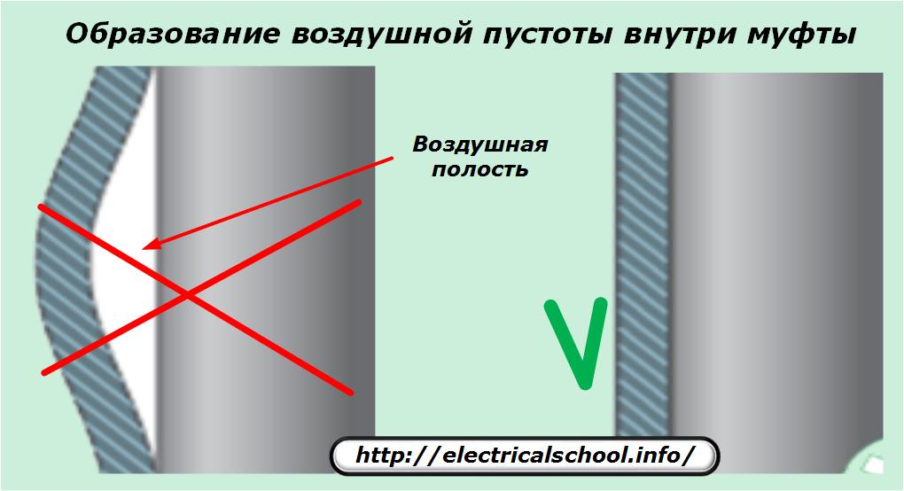
Air cavities in connectors
All spaces between connector parts must be completely filled with sealants. If air cavities are formed inside, then ionization will occur in them.
Thus, connectors for power cables must be installed according to strict rules in accordance with technological operations, which have been thoroughly studied and mastered in practice by specialists of electrical installation organizations, which are engaged only in connecting the ends of cables and lines from them.