Installation of open wiring in lighting networks
 In the lighting networks of industrial enterprises, depending on the characteristics of the environment, different types of wiring are used and different methods of laying wires and cables are used. In this case, they are guided by the requirements PUE.
The installation of lighting networks consists of performing the following operations:
a) markings in which the places for installing lamps, installation devices, group lighting points, routing wires, as well as the places for drilling holes, holes and channels are marked;
b) a detail consisting of the arrangement of through and socket holes, channels and niches, installation of fasteners, supporting structures and insulating supports, laying pipes and wiring pipes;
c) laying wires and cables on the finished part;
d) installation of lamps, installation devices and group lighting points for the finished part.
Layout work during the installation of open electrical cables
For general even lighting, the fixtures are usually positioned like this.See drawing.
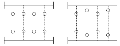
Layout options
The distance between the center lines of the fixtures is twice the distance from the same axes to the planes of the walls. Making such a decision will become obvious if we consider that the areas between the lamps are illuminated from two sides, and the area between the lamps and the walls is illuminated from only one side.
The data determining the location of the lighting fixtures by height are given in the figure.
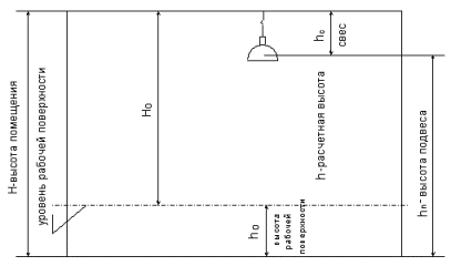
Rice. Suspension height data.
The place for installation of the lighting fixtures is determined according to the working drawings.
Markings on the trusses or joists of the workshop are made by pulling a cord or steel wire across the room so that they pass exactly through the center of a given row of lamps. Focusing on a marking cable or wire, mark the installation places of the lamps with chalk, pen or colored pencil. Another way of marking is also possible, for example, the location of the lamps is established by measuring from the plane of the walls.
Marking the locations of installation devices. Individual switches are usually marked at a height of 1600 — 1700 mm, contacts at a height of 800 — 900 mm from the marking of the finished floor. By the concept of a clean floor we mean the floor level of the room after its clean completion.
It is convenient to carry out work using a rail on which the corresponding dimensions are separated.
Switches and sockets may be mounted at other distances from the floor depending on local conditions and requirements.
Lighting panels or points without control are installed at a height of 2 - 2.5 m and with control at a height of 1.6 - 1.7 m from the finished floor to the centers of switches, handles of automatic devices or switches.
It is convenient to mark the installation locations of the devices using a marking template.
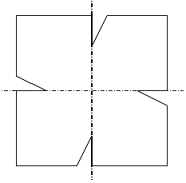
Rice. Highlight lines from transactions.
The routes of exposed wiring should pass in horizontal and vertical directions, combine with the architectural and construction details of the premises, and also be symmetrically located with respect to the structural parts of the equipment.
Marking of wiring paths is done by marking lines on the planes of the premises using painted cable.
When laying the wiring along the walls of the route, they must pass parallel to the connecting lines of the walls and ceilings at a distance of 100 — 200 mm from the ceiling or at a distance of 50 — 100 mm from the eaves.
The descent and ascent of the wiring to the lamps, sockets must be carried out in a vertical line.
The places for mounting the lighting fixtures on the ceiling are marked depending on their number. After determining the places for installing the lighting fixtures on the wall and ceiling, a line of future electrical wires is cut off with a cable. On the lines are marked the points of attachment of the wire, as well as the points of through holes for the passage of wires through walls and ceilings. Passages of wires through fire-resistant walls are made in rubber or polyvinyl chloride pipes and through combustible walls and ceilings in sections of steel pipes, at both ends of which insulating sleeves are placed. The pipe in the wall opening is sealed with cement putty. The insulating pipe should protrude 5-10 mm from the pipe.
Wiring
PPV and APPV conductors laid outdoors must have a light-resistant sheath.In the case of open laying, the distance between the individual wires for parallel laying should be at least 3 - 5 mm. it is not allowed to lay PPV and APPV wires in bundles. If the conductor is laid on uncoated wooden surfaces, the base of the wiring route must be lined with asbestos, protruding 5 - 6 mm from both sides of the laid wiring.
Before laying the wire, it is rolled out, measured in individual pieces in sections and then straightened using a special roller press or with a gloved hand on it. No significant effort should be applied to tamper with the wire, as the sheath easily slides off the live wires.
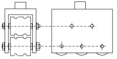
The measured and straightened is wound on coils and in this form is delivered to the place of laying. In open laying of PPV and APPV wires, the wire can be fixed with nails with a diameter of 1.4 — 1.6 mm with caps with a diameter of 3 mm. The nails are placed between the wires of the wire just along the center line of the separation film and driven with a mandrel to prevent the wire from being damaged by the hammer.
If the wiring is carried out in damp rooms, then it is recommended to place fibers or rubber pads under the heads of the nails.
Bending of PPV and APPV wires at the edge with open laying can be done by approximating by cutting the separation film. Bending by crossing the cores is prohibited.
When laying PPV and APPV wires at the entrances to the box at a distance of 45 — 50 mm from the separator, the separator is removed from the end of the wire, after which the wires are inserted into the box.
