Rules for carrying out work on the grounding device
Grounding device It is a set of grounding wires and grounding wires.
Ground switch — is a metal conductor in direct connection with earth.
Grounding wires are metal wires connecting the grounded parts of the electrical installation to the grounding electrode.
Grounding any part of an electrical installation is said to be intentionally electrically connected to a grounding device.
Voltage relative to the ground when short to the frame refers to the voltage between this case and grounding points that are outside the zone of currents in the ground, but not closer than 20 m.
Resistance of the earthing device This is the sum of the resistances consisting of the resistance of the earthing electrode to earth and the resistance of the earthing conductors.
Grounding Resistance — The ratio of the voltage across the grounding electrode to ground to the current flowing through the grounding electrode.
Artificial and natural grounding electrodes
Artificial ground electrodes are used when natural grounding do not meet the requirements PUE… As natural grounding electrodes are used: steel water pipes laid in the ground, connected at the joints by gas or electric welding; pipes from an artesian well; metal structures of buildings and structures that have a reliable connection to the ground; different types of pipelines laid underground.
Oil pipelines, gas pipelines, gas pipelines and the like are not allowed to be used as natural ground electrodes.
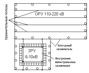
50 mm pieces of angle steel are used for artificial earthing. 2.5 - 3 meters long, which are driven vertically into a trench 70 cm deep, leaving 10 cm above the bottom of the trench. Round steel with a diameter of 10 — 16 mm is welded to these grounded electrodes, placed in a trench. or strip steel with a cross section of mm. along the entire contour.

Resistance of the grounding device
From PUE in electrical installations up to 1000 V with stable grounding of the neutral, the resistance of the grounding devices should be no more than 4 ohms. For electrical installations above 1000 V. with high earth fault currents, the resistance of the earthing device should be no more than 0.5 Ohm.
For electrical installations above 1000 V with low earthing currents, the resistance of the earthing device must meet the condition Rs < Uc /Azh, where Uz = 250 V. if the earthing device is used only for installations with a voltage above 1000 V, Uh = 125 V. if the earthing device is simultaneously used for installations up to 1000 V. I s — rated earth fault current.
If the grounding device is common to the distribution devices of electrical installations with different voltages, then the lowest of the required values is taken as the calculated resistance of the grounding. The capacitive earth fault current is determined by an approximate formula. Azs = U (35lx +lv) / 350, where U — network voltage of the network, lNS and lv - total length of cable and overhead lines electrically connected to each other, km.
Installation of the grounding device
All connections in the ground circuits are made by overlapping welding. The quality of the welds is checked by inspection, and the strength is checked by blowing with a 1 kg hammer. The welding points are coated with bitumen varnish against corrosion.
Assembly grounding and neutral protective conductors… Grounding wires are laid horizontally and vertically along building structures.

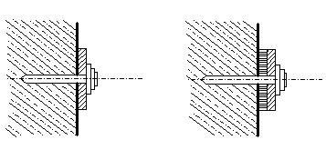
In dry rooms, the grounding wires are laid directly on concrete or brick walls with strips scattered under the dowel, and in wet rooms on pads at a distance of at least 10 mm. from the wall.
The conductors are fixed at distances of 600 — 1000 mm., on straight sections and 100 mm on bends, 400 — 600 mm from the floor level. Ground wires are bolted to the frames of machines and devices.
