Installation of overhead lines with a voltage of 0.4 — 10 kV
Electric networks (ES) located in open spaces outside buildings often operate overhead lines (HV)... For the length of the span of the overhead line on the ground, the horizontal distance between the centers of two adjacent supports is taken.
Anchor section called the sum of the lengths of the distances between the anchor-type supports. By the sag of the wire f with the same height of the half-weight points, we mean the vertical distance between the line connecting the suspension points and the lowest point of the wire. For the size of the H line, the smallest vertical distance with the greatest sag of the conductors to the level of the ground or the structures to be crossed is taken.
The angle of rotation of the route of the line refers to the angle between the directions of the lines in adjacent sections. Wire tension is understood as a force directed along the axis of the wire. The mechanical stress of the wire is obtained by dividing the stress by the cross-sectional area of the wire.
Intermediate supports installed on straight sections of the overhead line route.These supports under normal conditions should not perceive forces directed along an overhead line.
Corner supports installed in places where the direction of the route changes air line. These supports under normal conditions must perceive the tension of the conductors of adjacent sections.
Anchor supports installed at intersections of different structures, as well as in places where the number, brands and cross-sections of wires change. These supports should be perceived in normal operating modes from the voltage difference of the wires directed in the remote air connection. Anchor supports must be of rigid construction.

End supports set at the beginning and end overhead line. And also in places with cable inserts. They are anchor type supports. Branch supports installed in places of branching from overhead lines.
Cross supports installed at intersections overhead line in different directions.
Intermediate Span This is the horizontal distance between two adjacent intermediate supports. On an overhead line up to 1 kV, the section length is from 30 to 50 m, and on an overhead line above 1 kV, the section length is from 100 to 250 m.
Construction and construction of overhead lines
HV have the following structural elements: conductors, supports, insulators, fittings for fixing conductors on insulators and insulators on supports. VL are single-circuit and double-circuit. A circuit is understood as three conductors of a three-phase line or two conductors of a single-phase line. Aluminum, steel-aluminum and steel wires are used for overhead lines. Supports for overhead lines are made of wood and reinforced concrete. Wooden poles are easy to manufacture, cheap, but short-lived.Reinforced concrete supports are more expensive, but stronger.
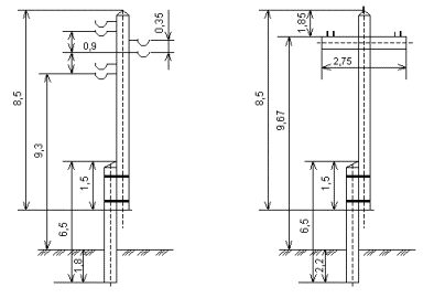
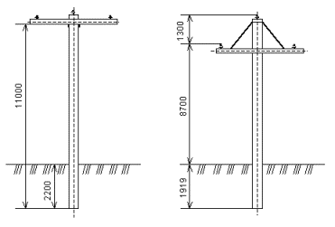
In the production of parts of wooden supports, coniferous wood is used. The main types of intermediate supports in fig.
The reinforced concrete intermediate supports are single-column with a horizontal arrangement of wires on pin insulators. The supports are designed for hanging wires of classes A25 — A70, AC16 — AC50 and PS25. pin height up to 175 mm. the pins are grounded by welding to the armature outlets from the reinforced concrete traverse.
For branches up to 1 kV, aluminum conductors and its alloys with a cross-section of at least 16 mm square can be used to the entrances of buildings.

Overhead lines use pin insulators, which are delivered to the installation site in grid boxes. Insulators are visually rejected before being sent to the runway.

Installation of power lines with a voltage of up to 1 kV
When the overhead line passes through forest and green space, clearance clearance is optional. The vertical and horizontal distances to the wires with the largest sagging arrow and a small deviation from trees and bushes should be at least 1 m.
Boreholes are drilled using drilling machines. If it is impossible to use drilling machines, the holes are dug by hand.
For single-column supports, pits are drilled exactly along the axis of the route. The drill bit during drilling is placed in a strictly vertical position.
The dimensions of the deepening of the supports are determined according to the table depending on the height of the supports, the number of wires attached to the support, the type of soil, and also the method of excavation. When manually digging holes, they are dug 30-50 cm deeper.
The traverses of the corner supports are located along the bisector of the angle of rotation of the line. Their serial number and year of installation are applied to the supports. The numbering of the supports comes from the power source.
Transoms, brackets and insulators are installed before lifting the support. Insulators are carefully inspected and discarded before installation. Insulators must not have cracks, chips, damage to the glaze. Cleaning the insulators with a metal object is not allowed. Pin insulators are screwed onto hooks or pins wrapped in the drawbar. The axes of the pin insulators are located vertically.
Rust protection hooks and pins are torn with asphalt varnish.
Fastening wires on pin insulators is done with wire ties.
Wires are connected by connecting clamps or welding. Wires can be connected by twisting with subsequent soldering. The attachment of the wires to the supports is single. Double fastening is carried out at intersections of overhead lines with communication and signal lines, contact wires, roads and in populated areas.
The supports, assembled and transported along the route, are installed along the route with the help of drilling and crane machines or mobile cranes.
Clip-on insulators fixed on hooks on the trunks of wooden supports without sleepers. Holes are drilled in the support with a drill, into which the tails of the hooks are screwed. The studs with insulators for mounting on sleepers are secured with a nut.
The construction of the overhead line is carried out by the flow method.The installation of wires is divided into operations: rolling wires, connecting wires, lifting wires to intermediate supports, tensioning wires and fixing wires to anchors and intermediate supports.
Stretching of wires from the drums is done by tractors or motor vehicles and is taken from one anchor support to another.
When unfolding, the places of the detected defects of the wires are noted. Repairs are carried out in these places before stretching.
Installation of overhead lines up to 10 kV
The excavation of the pits for the supports is carried out with a theodolite, a steel measuring tape or a tape measure according to the scheme, which shows the alignment axes and the dimensions of the pits above and below, taking into account the foundation used and the required steepness of the slopes. The dimensions of the bottom of the pits should not exceed the dimensions of the base plate of the foundation by more than 150 mm per side.
Excavation of pits with vertical walls without fasteners is allowed in soils with natural moisture in the absence of groundwater.
Mechanized excavation of the soil in pits is carried out without disturbing its structure at the base of the foundation. Therefore, excavations are carried out with a shortage of soil for a thickness of 100 — 200 mm. no soil development is allowed below the design level.
Excavated soil should be dumped at least 0.5 m from the edge of the pit to avoid the possibility of the pit walls collapsing.
Pine and larch are used for the production of wooden poles of overhead lines with a voltage of 10 kV. The wood for the production of supports is completely sanded and impregnated with an antiseptic for the stability of the support from rotting.
When crossing an overhead line with wooden supports, where ground fires are possible, the supports protect against burning. To do this, ditches with a depth of 0.4 and a width of 0.6 m are dug around each support at a distance of 2 m from it; areas with a radius of 2 m are cleared of grass and bushes around each support. Or, reinforced concrete attachments are used in these areas.
Before installation, reinforced concrete supports are carefully checked for the presence of shells and holes with a length, width and depth of no more than 10 mm. At the same time, there should be no more than two sinks and holes per 1 m of the length of the support. Sinks and holes should be sealed with cement mortar.
The main way to install single-column reinforced concrete supports is to install them in boreholes with undisturbed soil structure.
The distance from the underground part of the support of the overhead line to the underground sewage pipelines must be at least 2 m for an overhead line with a voltage of up to 10 kV.
When the overhead line approaches the main gas pipelines and oil products, the latter must be laid outside the overhead line security zone. For 10 kV overhead lines, the protective zone is 10 m. This distance is measured from gas pipelines and pipelines for petroleum products to the protrusion of the end conductors. In tight conditions, it is allowed to reduce the protective zone to 5 m for overhead lines up to 10 kV.
To protect against lightning surges, the following must be grounded: reinforced concrete supports overhead lines with a voltage of up to 10 kV in populated and uninhabited areas, reinforced concrete and wooden supports of all types of lines with all voltages on which lightning protection devices are installed, all types of supports on which power and measuring transformers, disconnectors, fuses and other equipment are mounted.
Overhead earthing devices are made of angle steel vertical earthing electrodes.
