Assembly and installation of overhead line supports
 For the construction of overhead lines with a voltage of up to 1000 V, wooden and reinforced concrete supports are used. The wooden supports are of different design (Fig. 1, a, b, c, d).
Softwood (larch, fir, pine, etc.) is mainly used for the production of wooden supports. The diameter of pine logs for the main elements of the supports (racks, attachments, crossbars, supports) of overhead lines up to 1000 V should be at least 14 cm, and for auxiliary parts (transverse beams, beam under the crossbar, etc.) — at least - a little 12 cm.
The wood of the posts is short-lived and for example the service life of untreated wooden pine posts is about 5 years. Dangerous wood destroyers include pillar fungi, pink ash fungi, dormant fungi, and insects such as hornet beetles, black barbels, and termites.
Increasing the service life of wooden poles by 3-4 times is achieved by treating them with various chemicals - antiseptics, the process of treating wooden poles is called antiseptic treatment. Creosote oil, sodium fluoride, uralite, donolite, etc. are used as antiseptics.
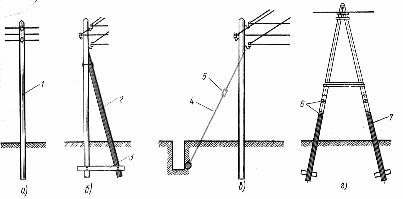
Rice. 1. Constructions of wooden supports of overhead lines up to 1000 V: a — single-pole intermediate, b — corner with bracket, corner with mounting, d — A-shaped anchor: 1 — rack, 2 — bracket, 3 — crossbar, wire, 5 — tensioner, b — bandages, 7 — attachment (stepchild)
Wooden poles are made, antiseptic and assembled at special depots and construction enterprises, and then delivered to the installation site by vehicles with trailers.
Single-column wooden supports are delivered to the track assembled, and multi-column (A-shaped, etc.) - partially assembled. These supports are assembled on site.
Before installation, all parts of the support are carefully checked: they should not have such defects as destruction of protective coatings (antiseptic, anti-corrosion), damage to the threads of bolts and bolts, deep cavities on metal brackets and bandages, etc. During work, a section of a wooden support located 30-40 cm below and above the ground level is damaged most quickly, that is, in a place where the wood is most intensively exposed to the variable effects of atmospheric precipitation and moisture contained in land.
In order to save wood, wooden supports are made composite — they connect the supporting stand with a wooden or reinforced concrete attachment (step). Composite supports form a solid structure, the use of which increases the reliability of the overhead power line and its service life.
The connection of the support post with one or two attachments (Fig. 2, a, b) is carried out with bandages or clamps. To connect a wooden rack with a wooden attachment, the applied part of the rack 1.5 — 1.6 m long is pressed against a plane with a width of 100 mm.The upper part of the wooden attachment is machined to the same length and width.
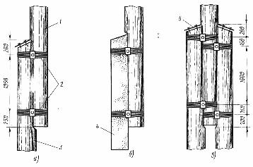
Rice. 2. Methods of pairing wooden supports with attachments (steps): a — with one wooden, b — with one reinforced concrete, with two wooden, 1 — stand, 2 — bandages, 5 — wooden attachment, 4 — reinforced concrete attachment, 5 — a layer of cover paper.
The beveled planes of the rack and attachment must end with a perpendicular notch. The joint of the parts to be joined must be tight without gaps. From both parts, the lines of the strips are marked and small recesses are made for the bolts that tighten the strips. The recesses for the bolts are made in the case that the tightening of the bandages is done not by twisting, but by bolts.
Along the circumference of the trunk and attachments along the width of the strips (50 — 60 mm), they remove the unevenness to ensure a better tightening of these supporting parts of the strips.
The bandages are placed on the interface in two places, offset from the top of the attachment by 200 mm and above the butt of the support post by 250 mm. The distance between the strips is 1000 — 1100 mm.
For bandages, steel galvanized soft wire with a diameter of 4 mm or non-galvanized wire (wire rod) with a diameter of 5 — 6 mm is used.
The tie consists of several turns of wire applied to the section where the support post connects to the attachment and tightly twisted or tightened with a through bolt. The number of turns of each sheath is determined by the diameter of the sheath wire. One strip should have 8 turns with a wire diameter of 6 mm, 10 turns with a diameter of 5 mm and 12 turns with a wire diameter of 4 mm.
The length of wire required for one strip is calculated by the formula:
Lb = 26n (D1 + D2)
where Lb — length of the wire, cm, n — the number of turns of the tape, D1 and D2 — the diameters of the trunk and attachment at the place of installation of the bandage, see
The dressing is applied to the support as follows. The end of the jacket wire is bent to a length of 3 cm at a right angle and driven into a wooden attachment (when the support post is connected to a reinforced concrete attachment, the end of the jacket wire is driven into the support post), and then, after winding and tightly laying the required number of turns, push them in the middle and insert a special lever with a bent end into the resulting space between the turns, turn all the turns.
After applying the second dressing as described, the abutment is turned over and both dressings are twisted with a lever on the other side of the abutment, thereby firmly tightening the bandages at the interface of the abutment post with the attachment. Instead of twisting, a socket head bolt, washer and nut can be used to tighten the bandage.
Pairing the support stand with two attachments (Fig. 2, c) is done in the same way as when pairing the support with one attachment, while the support column is processed on both sides.
Each attachment is attached to the rack with separate bandages, for the placement of which, in the corresponding sections of the attachments, cuts with a depth of 6 — 8 mm and a width of 60 — 65 mm are made in advance. The mating points of the supporting parts, cuttings, cuts and curtains are covered with an antiseptic.
Washers are placed under the nuts and bolt heads. The wood under the washers should be cut, but not cut.At a height of up to 3 m from the ground, the threads on the ends of the bolts protruding from the nuts are sealed, the ends of the bolts protruding from the nuts by more than 10 mm are cut off and also sealed. The non-galvanized metal parts of the supports are twice coated with asphalt-bitumen varnish.
For convenience when applying wire strips, the support should be raised above the ground by 20-30 cm, and the attachments should be temporarily connected to the support stand with the help of clamps (Fig. 3, a).
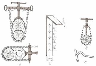
Rice. 3. Devices for assembling and equipping wooden supports: a — clamp for temporary fastening of a support post with a wooden and reinforced concrete attachment, b — template for marking holes for hooks, c — device for manually drilling a hole in a support, d — key (screw) for screwing the hooks into the support
The equipment of the supports is carried out during their production in construction enterprises, but not infrequently, in order to avoid damage to insulators and fittings during transportation, directly to the place of construction of the overhead power line.
The work of equipping the supports includes marking the locations of the hooks, drilling holes in the support for the hooks and installing hooks with insulators in them.
The place for mounting the hooks on the support is marked using a template made from a piece of rectangular aluminum rail with a thickness of 3 — 4 mm. A template (fig.3, b) with a short curved end is placed on the upper part of the support, first on one side, and then on the other side, marking the places for installing the hooks on the even and odd holes of the template, respectively. The holes in the crossbars for installing the pins in them are also marked using a template.
Holes in the support are drilled using an electrified tool, in the absence of a power source, a drill of a suitable size or a special device is used (Fig. 3, c).
The hole drilled in the support should have a diameter equal to the inside diameter of the hook thread and a depth equal to 3/4 of the length of the hook thread. The hook must be screwed into the support body with the entire threaded part plus 10 — 15 mm. The hooks are screwed into the hole using a wrench (Fig. 3d).
Insulators are mounted on fittings (hooks, pins) in workshops or directly on the route of the overhead line when equipping supports. Insulators should not have cracks, porcelain chips, stubborn dirt and other defects that cannot be cleaned.
Dirty insulators must be cleaned. Cleaning insulators with metal brushes, scrapers or other metal tools is prohibited. Most contaminants are removed from the surface of the insulator by wiping the contaminated areas with a dry cloth and a cloth soaked in water, and stubborn contaminants (rust, etc.) moistened with hydrochloric acid. Work with hydrochloric acid should be done with acid-resistant rubber gloves and goggles.
Insulators and fittings (Fig. 4) are selected taking into account the calculated loads from the voltage of the wires, the ice area (the mass of possible ice formations on the wires is taken into account), the wind pressure on the wires, etc. In this case, take the following values of the factor of safety against the breaking load: 2.5 with normal conductor tension and 3.0 with weakened conductor tension.
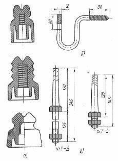
Rice. 4.Insulators and fittings for overhead lines up to 1 kV: a — insulators TF, RFO and SHFN, b — hook KN -16, c — pins SHT -D (for wooden sleepers) and PGG -S (for steel sleepers)
Wooden poles are widely used in the construction of overhead lines, especially in areas rich in forests, but, as already stated, wooden poles are short-lived, so they are gradually being replaced by reinforced concrete poles, whose service life is 50-60 years.
Reinforced concrete supports of overhead lines with a voltage of up to 1 kV have a conical shape and a rectangular or ring-shaped (circular) cross-section. To lighten the mass, the rack of the reinforced concrete support is made hollow for a significant part of its length.
Reinforced concrete supports are equipped with a rigid metal frame made of reinforcing steel, which increases the mechanical strength of the support, they serve to hang wires on them on crossbars or hooks: in the latter case, holes are left in the support body during its manufacture for installation on hooks in them.
The reinforced concrete support has a special terminal welded to the frame reinforcement to connect it to the neutral conductor of the grounded neutral line. A reinforced concrete support is installed in block foundations or directly in the ground with a reinforced concrete slab underneath.
The rigging of reinforced concrete supports is carried out in almost the same way as the rigging of wooden supports, differing slightly only in some minor operations. Work on the equipment of the supports is carried out before they are lifted and installed in the pit, which allows the use of various mechanisms and thus greatly facilitates the work of the installers.