Installation of wires on overhead lines
 For overhead lines with a voltage of up to 1 kV, mainly aluminum, steel-aluminum and steel conductors are used.
The complex of works on the installation of overhead line wires includes: rolling along the route of the overhead line and connecting the wires, lifting, adjusting the sag and fixing the wires to insulators.
Wires are rolled from both sides of the installed supports along the overhead line. Conical rotors or portable machines are used for winding coils of wires, and for wires delivered to the track in drums, a collapsible drum hoist is used.
With a line length of no more than 0.5 km and a wire cross section of up to 50 mm2, a turntable, machine or drum with wire is installed on a drum lifter at the first support at the beginning of the line and, catching the end of the wire, pull it to the last support, i.e. to the end of the line. With a long line, these devices are placed in the passenger compartment of a car with the tailgate down, and as the car moves along the supports, the wire is unwound, making sure that no loops ("lambs") form in the wire.
Simultaneously with the rolling of the wire, it is carefully inspected to identify defects in the wire in the form of breaks in individual cores, large dents, etc. Defects found in the wire are marked with paint and then removed before the wires are removed raised to the support.
If the wire is delivered to the workplace in a drum mounted on jacks, it is rolled out without removing it from the car, having previously raised the drum 10-15 cm above the floor of the body with the help of jacks and a pipe threaded through an axial hole in the drum.
The end of the wire, unwound from the drum before the start of the car's movement, is attached to the anchor support, from which the wire is rolled to the supports following in the direction of the track of the overhead line. If the length of the rolled wire turns out to be insufficient, then a wire of similar design, make and section from another drum is connected to it.
To connect wires from overhead lines up to 1 kV, use: twisting, banding, connection in an oval connector (sleeve) with subsequent crimping and welding of the ends of the wires in a loop, butt welding of the ends of the wires and their subsequent crimping together with a shunt in two separate connecting sleeves, butt welding the ends of the wires and crimping them together with an insert in an oval connecting sleeve, overlapping wires with crimping in a connecting sleeve, connecting wires with a bolt clamp.
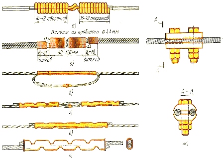
Rice. 1. Connecting wires of overhead lines up to 1 kV: a — twisting, b — shaping, c — pressing into a sleeve and welding into a loop, d — pressing the wire together with a shunt, e — butt welding and crimping into a sleeve, f — overlapping crimp in sleeve, g — bolt clamp
The twist (Fig.1, a) is the simplest way to connect single-wire steel and bimetallic wires, in which the ends of the wires are overlapped for a length of 180-200 mm, and then they are clamped with pliers in the middle of the connecting section, one wire is wound on the other (to the left and right of the pliers), placing the turns tightly to each other.
Dressing (Fig. 1, b) is used when connecting single-core wires. The ends of the wires are bent at right angles and placed on top of each other at a length of 80-120 mm, depending on their cross section. Then 5 — 6 turns of soft galvanized wire with a diameter of 1.5 mm are wound on one of the wires to be connected and transferred with this wire to the bandage of the connecting section. After covering the entire length of the connection with wire turns, make 5 - 6 turns on the second of the wires you need to connect. To increase the strength of connecting copper wires over long distances, the bandage is soldered with POS-ZO or POS-40 solder.
Connections in an oval sleeve (Fig. 1, c) are used for multi-core aluminum wires. To complete the connection, the wires are inserted into an oval sleeve corresponding to the cross-section of the wires and pressed forward to each other so that the ends of the wires come out of the opposite (outlet) holes of the sleeve. Then the sleeve is crimped, and the free ends of the wires are butt-welded into the loop.
Connecting wires by crimping in two sleeves together with a shunt (Fig. 1, d) is mainly used when installing multi-core aluminum wires with a cross section of 70 mm2 and more. The operation of pressing the bushings is carried out by means of crimping mechanisms.
The connection of wires in an oval sleeve by preliminary butt welding of wires and subsequent pressing of the sleeve and wires together with an insert (Fig. 1, e) is most often used in the middle of a large section when installing multi-core wires from overhead lines located in III or IV region of ice and with possible exposure of the conductors of the line to high wind loads.
Connecting wires by overlapping crimping in an oval sleeve (Fig. 1, e) is the simplest method used in the installation of multi-core wires with a cross section of 16-50 mm2.
Shown in fig. 1, a, b, c, d, e, f methods can be used to connect wires in the range of overhead lines. Bushings and wires must be of the same metal: copper (COM) — for copper wires, aluminum (SOA) — for aluminum, steel (SOS) — for steel.
Connecting bare wires can also be done using bolt clamps. A bolt clamp (Fig. 1, g) is allowed to connect wires only on supports and provided that the wires will not experience mechanical stress. The bolt bracket consists of two or three (depending on the cross-section of the wire) galvanized bolts with nuts and two dies with longitudinal grooves.
In order to ensure the necessary contact in the bracket, the diameters of the holes formed when connecting the dies must be slightly smaller than the diameters of the wires. When installing the clamps, the contact surfaces of the matrices immediately before connecting the wires are washed with gasoline and lubricated with a thin layer of technical petroleum jelly.
The surfaces of the clamps for connecting aluminum wires are cleaned with a steel brush on a layer of petroleum jelly, and the surfaces of the wires are also processed. The bolts must be tightened with a wrench with a force not greater than 25 kgf. In this case, it is not allowed to use devices that increase the clamping force in order to avoid crushing the connecting wires or breaking the thread of the bolts. The threads of the bolts and nuts of the bracket must be lubricated with petroleum jelly or grease. The use of lock nuts is mandatory.
After tightening the bolts, a gap of 3 — 5 mm should remain between the dies. A full fit of the clamping dies will indicate the absence of the necessary contact and the clamp should be replaced. To protect the contact surfaces from oxidation, the external gaps and the places where the wires exit the clamp are covered with a 1-3 mm layer of paste - red lead diluted with natural drying oil.
After 8 — 10 days after installing the bracket, it is recommended to additionally tighten its bolts, because due to the decrease in the elasticity of the wires, the pressure between the dies and the wires will slightly decrease, which will lead to a deterioration of the contact between them and possible heating of the connection area.
When deploying overhead wires, it is often necessary to cross railway tracks, highways with heavy traffic, as well as communication lines, the operation of which cannot be interrupted even for a short time. In such cases, temporary transition devices are constructed for coiling the wires.
In the vicinity of operating overhead electrical networks, catenary networks, electrified transport and open substations, the wires must be wound with special precautions to exclude the possibility of accidental contact of the wires mounted on the live parts of these electrical installations.