Installation of internal connections for control cabinets
 When installing boards, devices, secondary circuits, the following rules must be observed:
- before starting work, it is necessary to study the working drawings, technical documentation,
- all devices located in the drawer or cabinet are interconnected with integral jumpers without leading wires to the tuning brackets. Circuits for connecting external devices are connected to the clamps of the strips (rails). Straighten the wires before laying and wipe them with a rag soaked in paraffin,
- on the panels of the cabinets, the wires are laid only vertically and horizontally. The bending radius of the wires is at least three wire diameters. The wires are fixed to the panel with clamps with insulating gaskets. Streams of wires are fixed with bandages every 200 mm.
- the transition of wires from the body of the board to the movable door or movable contacts of the device is carried out with flexible copper wires in the form of a vertically twisted bundle without cutting the wires.
The belt is attached to the body and the door with a clamp. The fixed body of the control box is connected to the door by means of a stranded cable. The rings at the ends of the core are placed in the clamp along the screw, which is tightened tightly, preventing the core from "squeezing out" or the strand from breaking.
If two wires are connected to the wire, a washer is placed between the rings. Connecting more than two wires with one screw is prohibited. It is not allowed to bend the wires or make rings on them with pliers or wire cutters.
The wires of the set clamps of the apparatus must have a marking that is written on the plastic rings with a composite inscription or from a polymer tube 20 mm or 15 mm long.
The inscriptions on the end tubes are applied on both sides with indelible ink. It is forbidden to hang tags on the wires instead of the rings.
Switches and control switches are connected in accordance with the contact closure diagram shown in the schematic drawing.
The use of wires and cables with aluminum conductors for internal installation of distribution devices is not allowed.
Installation of connections in switchgear.
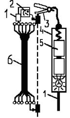
1 From electric circuit diagram the connection diagram is drawn up by the address method (Fig. 1).
2 The box panel contains the necessary electrical devices.
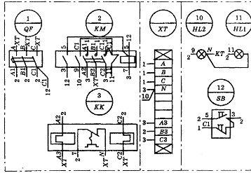
Figure 1. Wiring diagram of the electric drive control box
The route along which the wires will be laid has been outlined. The necessary measurements are made on the panel and a sketch of the harness is prepared in accordance with the route obtained (Fig. 2).
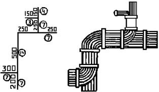
Figure 2.An example of drawing up sketches for the preparation of wires: a) sketch, b) general view.
On the sketch, the lines are marked with the length of the section in mm, and in a circle - the number of wires in the section (determined according to the connection scheme made at address).
3. On a universal template, which is a perforated plate with holes with a diameter of 3 — 5 mm, located at a distance of 25 — 50 mm, a rope outline is applied with chalk. The end and corner spikes are exposed.
4. Selected wires for installation of the main current and secondary circuit. In accordance with the sketch, wires are cut to the required length, wiped with a rag soaked in paraffin and straightened.
5. The wires are marked. Slide each end of the wire with a label tube and apply indelible ink to match the wiring diagram markings.
Marking on panels, consoles, devices, devices is applied with paint on a template, on cables - with hanging labels or inscriptions on the cuffs of the terminals, on wires and wires - with an inscription of signs on the terminators, polyvinyl chloride pipes, on the insulation of the wires with a marking Adhesive tape.
To indicate the phases or polarity, the wires are marked with paints of different colors or wires with colored insulation are installed (for phase A — yellow, B — green, C — red). DC circuits are distinguished by using wires with blue insulation (minus) and red insulation (plus).
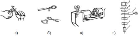
6. Wires are placed on the template in accordance with the drawn sketch. The wires are connected in a bundle (with a thread bandage, perforated tape, yarn tape, etc.) fig. 3. With the help of a board and a wooden hammer, the threads of the wires are leveled.
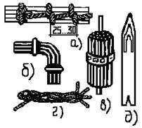
Rice. 3.Fastening bundles: a) knitting a bundle with threads, b) flat, c) perforated tape, d, e) shuttles
7. The insulation is removed from the ends of the wires. Tester or megohmmeter The assembled harness "rings" and the marking of the wires is checked (Fig. 4).
Rice. 4. Wiring continuity diagram: 1 probe, 2 device, 3 clamp, 4 indicator, 5 battery, 6 cable.
The winding of the core of extended circuits is carried out as follows: one end of the core is connected to the body, and the other end is located from the probe of the device, provided that the other probe is connected to the body of a control panel. Short circuits can be checked with a light bulb and battery (continuity test). In addition, there are special devices for finding the markings of the wires of the harness. For example, UMMK-55.
The wires in the bundle are interrupted (with a pin or a ring), depending on the type of their connection with electrical devices and devices Fig. 5. Stranded copper wires must be soldered.
Rice. 5. Sequence of crimping operations in ring ears: a) removal of insulation, b) twisting and laying in the tip, c) crimping with pliers, d) connection of aluminum wire, 1 — pin terminal, 2 — nut, 3 — finished wire core, 4 — washer, 5 — spring washer.
The harness is transferred to the panel of the box and the wires are connected to the terminals and terminals of devices and devices, fig. 6. No more than 2 wires can be connected to one outlet.
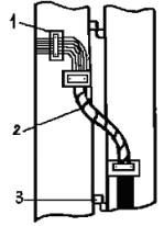
Rice. 6. Transition of wires to movable structures: 1-bracket, 2-bundle of wires, 3-shades.
Soldering of loose connections (butt or overlap) is not allowed.With a close arrangement of the contacts, the cores are fixed and after soldering, the polyvinyl chloride tube is pulled over the core. Short jumpers between adjacent contacts can be made by extending the connecting wire.
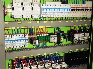
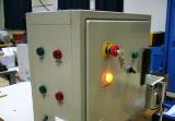
Rice. 7. Wires and electrical devices in the control cabinet
At the end of the installation, quality control is performed. At the same time, an external inspection checks the marking of the wires according to the connection scheme, the absence of undercuts of the conducting wires, the quality of their tinning, the absence of damage and contamination of the insulation.
The mechanical strength of the wire soldering is checked with tweezers with polyvinyl chloride tubes placed on its ends. The tensile force along the axis of the wire should be no more than 10 N. It is forbidden to bend the wire from the place of soldering.
After checking the soldering, the seam is painted with a transparent color varnish. The accuracy of cable connections is determined with a tester.
The control is as follows: first, the end of the wire is connected to one terminal of the tester circuit, the direction of which must be determined. Then to the ends of the wires located in another part of the device or a complete device, the second wire of the tester is connected in turn. When the circuit is closed by a wire, the tester will show the minimum resistance value. This makes it possible to make sure that the given ending is the desired one.