Installation of devices and systems for automation of electrothermal installations
 The installation of devices for measuring and regulating temperature in electrothermal installations can be carried out on pipelines, equipment, on the wall, on boards and consoles.
Installation of temperature control devices, as a rule, is carried out according to standard drawings, which are divided into standard assembly (TM), standard constructions (TC) and built-in constructions (ZK).
Three groups of numbers are included in the designation of typical drawings: the first group is the index of the organization that developed this drawing, the second group is the serial number of the drawing, the third group is the year of development. For example: TM 4-166-07, means — TM — typical assembly drawing, 4 — the index of the organization that developed the drawing (GPKI «Proektmontazavtomatika»), 166 — the serial number of the drawing, 07 — the year of development.
Typical installation drawings contain information on the method of installation, scope and number of a typical or built-in design, as well as explanatory instructions, notes and specifications indicating their type and quantity.
Drawings of typical structures determine the design of nodes or products intended for installation of automation equipment on them. They are the basis for the production of assemblies and products in the conditions of assembly and order workshops.
Drawings of built-in structures are intended for organizations that manufacture and install pipelines and equipment. According to them, suppliers of process pipelines manufacture and install built-in structures for the subsequent installation of tools and automation equipment on them.
Typical drawings, depending on the purpose and method of installation of automation devices, are grouped according to three technological characteristics: 1 — installation on process pipelines and equipment, 2 — installation on a wall, 3 — installation on boards and consoles.
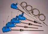
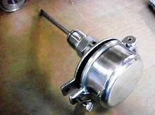
On process equipment and pipelines, submersible devices are mainly installed with a throttle valve.
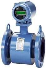 Chamber-type devices and some primary transducers are installed on the wall. Installation of such devices is usually done on a bracket. Secondary devices are installed on boards and consoles. When installing temperature measuring devices, keep in mind:
— the requirements specified in the typical assembly drawings,
— the requirements of the technical conditions and instructions for the operation of the devices.
The general technical requirements imply:
a) it is not allowed to install devices in premises with unfinished construction and finishing works, as well as before the completion of the installation of technological equipment and pipelines,
b) the devices are installed strictly in accordance with the technical conditions for climatic characteristics, placement category, degree of protection, level of vibration and shock loads,
c) devices supplied for installation must pass an external inspection and pre-installation wall inspection which determines their suitability for installation,
d) the depth of submerged thermometers and thermocouples in the measured medium should be such as to ensure the perception of the average temperature of the flow (usually in the center of the flow) and in places where the flow of the measured medium is not disturbed when the shut-off and regulating valves are opened valves, no leakage of outside air occurs. Usually, the installation location of the primary converter should be at a distance of 20 pipe diameters from valves, valves and openings,
 e) the devices must not be affected by external heat sources as a result of radiation and radiation. In cases where this cannot be avoided, the primary converters are protected by protective screens,
f) when the temperature of the streams of dusty media and granular substances changes in the places of installation of the primary converters, special barriers must be provided to prevent abrasive wear,
g) it is not recommended to install primary temperature converters in recesses and other places where stagnant zones are possible and air circulation is impeded.
In the event that it is impossible to install the sensor in the center of the flow, it is directed against the flow and installed at an angle of 30 or 45 degrees to the axis of the pipeline or placed in the elbow of the pipeline with an upward flow.
If the length of the device is much greater than the diameter of the pipeline, then a special device is used - an expander.
When installing the device on a process pipeline, the required depth of immersion must be observed (as a rule, the end of the immersed part, depending on the type of device, must be located from 5 to 70 mm below the axis of the pipeline along which the measured medium is moves).
Compliance with this condition can be achieved by using different methods of installation (installation) of temperature measuring devices). Wall-mounted temperature measuring devices are mounted on standard structures: frames or brackets.
The frame is attached to a brick (concrete) wall by aiming with dowels from a construction and assembly gun, the frame is attached by welding to a metal wall or structure using a bracket.
The bracket for mounting devices on the wall has 10 standard sizes, depending on the dimensions of the body of a particular device, the location and the diameter of the holes for its mounting. The bracket is attached in the same way as the frame.
 When placing temperature measuring devices on boards and brackets, the ease of maintenance, the design features of the boards, brackets and the devices themselves, as well as safety requirements, are taken into account.At the same time, design standards are widely used, taking into account the necessary distances between devices.
The installation of temperature measuring devices on process equipment, pipelines is carried out, as a rule, with the help of built-in structures - bosses. Boss is a part that is welded into an opening or on the surface of a process pipeline. The recess is threaded to secure the primary transducer through the mounting nipple.
The sizes and shapes of fittings for measuring devices are determined by GOST 25164-82 "Instruments and devices. Connection «. By type and parameters, welding channels are divided into straight (BP) and beveled (BS). They are of the first value (BP1 and BS1) for pressures up to 20 MPa, the second value (BP2 and BS2) for pressures from 20 to 40 MPa and for atmospheric pressure for surface primary transducers.
For surface primary transducers, the recesses may have the following thread sizes: M12x1.5, M18x2. The height of the recesses: BP1 — 55 and 100 mm, BP2 — 50, 60 and 100 mm, BP3 — 25, BS1, BS2 — 115 and 140 mm. The height of the recesses is selected from the thickness of the insulation layer on the pipeline. The installation of the most widely used instruments for measuring various parameters is carried out according to standard schemes.
Organizations assembling technological equipment carry out installation of prefabricated built-in structures according to standard assembly drawings. Built-in structures are mounted on tanks by welding. Separate devices are fixed on the elements of buildings and structures with the help of various clamps, legs, etc.