The use of trays in the installation of cable lines
 Installation of cable trays. The use of trays for laying wires and cables in them is becoming more and more widespread. This power drain system is very flexible, making installation and operation much easier.
The wiring in the trays provides good cooling conditions for the wires and cables, while the multiple rows of wires and the ability to arrange power and control cables and wires in the same tray provide great cost savings and lower labor costs compared to other systems for energy distribution. It also creates free access to wires and cables along their entire length, which is essential for the functioning of the wiring.
If necessary, wires or cables can be easily removed and quickly replaced with others, and their number, section and brand can be changed. Trays for laying wires and cables reducing the consumption of scarce steel pipes. The use of trays makes it easier to carry out postings along complex routes.
The range of trays is wide.They are intended for open laying of wires and cables where, according to current regulations, wiring in steel pipes is not required. Trays are installed in dry, humid and hot rooms, in rooms with a chemically active environment and in fire-hazardous rooms for laying wires and cables approved for these rooms. Trays are installed in electrical rooms, including cable floors and basements of electrical machine rooms, in passages behind shields and panels of control stations and transitions between them, in technical floors of buildings and structures, in machine rooms and their basements, in pump and compressor rooms premises, for internal shop wiring above metal cutting machines, etc.
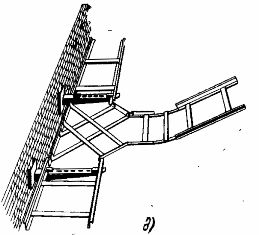
The trays are produced welded and perforated in four variants (fig. 1). The welded trays are a metal construction of two Z-shaped sections 1.6 mm thick and perforated cross bars welded every 250 mm to the longitudinal sections by spot welding. Perforated trays are 1.2mm thick perforated steel strip with right angle bent edges to increase structural rigidity. The trays are equipped with connecting brackets and bolts to connect the trays to the main lines.
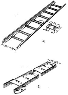
Rice. 1. Trays for wires and cables: a — welded tray; b — perforated tray.
Supporting structures for the installation of trays are elements of prefabricated cable structures, as well as brackets made in the workshops of assembly organizations from perforated or rolled profiles (Fig. 2).
The electrical installation rules standardize the dimensions for mounting trays, which are mandatory when marking trays on trays.The structures are attached to the foundations of the building at such a height that the distance from the trays to the floor or service area is at least 2 m.
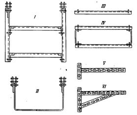
Rice. 2. Tray mounting structures suspended for perforated trays; I — IV — suspensions; V -VI — brackets.
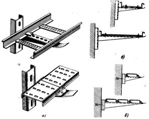
Rice. 3. Examples of single-stage installation and fastening of trays: a — fastening of welded and perforated trays on cable shelves; b — horizontal wall installation on cable structures made of welded trays; c — the same perforated trays.
In the electrical, as well as in other rooms, which are served by specially trained personnel, the height of the trays is not standardized.
When crossing trays with pipelines, the distance from the pipeline to the nearest wire or cable must be at least 50 mm, and when laying parallel to the pipelines, at least 100 mm from them. If the pipelines contain flammable liquids or gases, these distances are increased: when crossing, they must be at least 100 mm, and when they are placed in parallel, at least 250 mm. The distances between the attachment points of the trays are not standardized, but are usually 1.6-2 m.
Structures and brackets for mounting trays are attached to the foundation of the building with dowels, plugged with a structural and assembly gun, by welding to built-in parts or metal structures, on expansion dowels. Welded trays are attached to prefabricated cable structures or mounting profiles with special clamps. The bends and branches of the trough highways are made with the help of perforated mounting strips.
Examples of tray installation are shown in fig.3 and the implementation of bypasses, rotation, transition from one tray width to another, connecting and branching trays are shown in fig. 4. Trays intended for installation on cable shelves are pre-connected in several parts in sections, which are lifted on supporting structures and fixed with bolts and nuts through perforations using crackers or corners from the mounting profiles. The trough line is connected to the ground loop at least at two points on opposite sides. In addition, the trays of each branch are grounded at the end.
Rice. 4. Examples of installation of trough highways: d — branch.
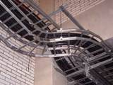
Trays for laying wires and cables are 2 m long, and the standard step of building structures is 6 m, therefore, when installing trays through floor trusses, in order to avoid cable sagging, it is necessary to increase their rigidity. The stiffness of the trays can be increased by suspending cables stretched across them or by laying on angle steel trays from truss to truss or between joists. It is more convenient to suspend trays between trusses or beams on cables or wire, as shown in fig. 5.
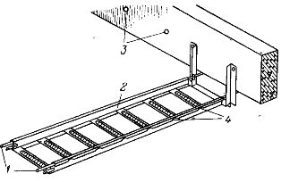
Rice. 5. Installation of trays on a cable (wire) under the ceiling. 1 — strings; 2 — tray; 3 — built-in holes in the beams; 4 — bending the flange of the tray around the wire rod.
Between the beams, two strings are pulled along the width of the board from a cable or a wire rod with a diameter of 8-10 mm. The strings are clamped to the U-braces mounted on the beams. U-braces are attached to the joists by through-bolts through built-in holes or dowels driven in with a construction and installation gun. The strings are stretched at one or both ends of the chute.After laying and connecting the trays, the edges of the beads are folded around the wire rod every 500-800 mm.
Laying wires and cables in trays has a number of advantages over laying them directly on prefabricated cable structures:
- the possibility of laying along complex routes (for example, in workshops with a large amount of equipment, where it is difficult to install cable structures);
- economy of cable structures (the distance between them is up to 2 m instead of 0.75 m when laying cables on the shelves);
- attachment and exit of cables at any point of the route as a result of perforation of trays;
- sagging and bending of wires and cables is excluded, which increases the duration of their service.