Selection of motors for elevators and lifting machines by power
 Modern passenger and freight elevators of residential and administrative buildings, as well as some machines for lifting mines, are performed with a counterweight or, as it is sometimes called, with a counterweight. In mining machinery, balancing, as already noted, is often done not by a counterweight, but by a second lifting vessel.
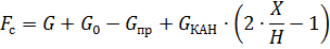
The counterweight for elevators is selected to balance the weight of the lifting vessel (car) and part of the nominal load to be lifted:
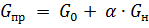
where GH is the weight of the nominal lifting load, N; G0 — cabin weight, N; Gnp is the weight of the counterweight, N; α is the balancing factor, usually taken equal to 0.4-0.6.
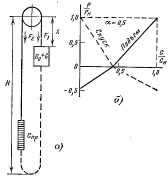
Rice. 1. To calculate the load on the elevator motor shaft.
The need to balance heavy ships is obvious, since to move them in the absence of a counterweight, a corresponding increase in engine power is required. The ability to balance a portion of the rated payload is revealed when determining the equivalent power for a given load curve.It is not difficult to follow, for example, that if the elevator works mainly to raise the load and lower the empty car, then the equivalent engine power according to the load diagram has a minimum at α = 0.5.
The presence of a counterweight leads to a flattening of the engine's load curve, which reduces its heating during operation. Referring to the diagram shown in FIG. 1, a, then with the weight value of the counterweight

and the absence of a balancing rope and cabin friction and the counterweight on the guides, you can write:
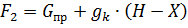
where gk is the weight of 1 m of rope, N / m.
Tensile strength

Motor shaft torque and power are determined based on the following formulas:
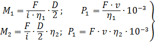
where M1, P1 — torque and power when the drive operates in motor mode, Nm and kW, respectively; M2, P2 — torque and power when the drive operates in generator mode, Nm and kW, respectively; η1, η2 — worm gear efficiency with direct and reverse energy transfer.
The values of η1 and η2 nonlinearly depend on the speed of the worm shaft and can be calculated by the formulas
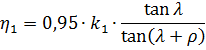
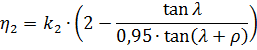
here λ is the angle of ascent of the spiral line on the indexing cylinder of the worm; k1 is a coefficient that takes into account the losses in the bearings and oil bath of the gearbox; ρ — angle of friction, depending on the speed of rotation of the worm shaft.
From the formula of the force on the traction sheave, it follows that in the absence of a balancing rope, the load on the electric drive of the lifting winch depends on the position of the lifting vessel.
Due to their large load capacity — up to 10 tons, high movement speeds — 10 m / s and more, high lifting heights of 200-1000 m and harsh working conditions, mine lifting machines are equipped with steel ropes with a large mass. Imagine, for example, that one pass is lowered to the lower horizon, while the other is above, and at that moment it is unloaded. In this position, the entire head rope is unbalanced, and at the beginning of the ascent the motor must overcome the static moment generated by the weight of the load and the rope. Balancing the rope takes place in the middle of the path of the skips. Then it breaks again and the weight of the descending part of the rope will help unload the engine.
Uneven loading, especially in deep mines, leads to the need to overestimate the engine power. Therefore, at a lifting height of more than 200-300 m, it is recommended to balance the head lifting ropes with the help of tail ropes that are suspended of the lifting vessels. Usually, the tail rope is selected with the same cross-section and length as the main one, as a result of which the lifting system turns out to be balanced.
Since the load changes during the operation of elevators and lifting machines, in order to determine the power or moment of the motor shaft for each load, it is convenient to build a graph of the dependence of these values \u200b\u200bon the load at several points, which has approximately the same character as shown in fig. 1b and then use it in constructing load diagrams.
In this case, the operating mode of the electric drive of the lifting machine must be known, which is largely determined by the relative duration of the PV activation and the number of starts per hour of the motor. For elevators, for example, the operating mode of the electric drive is determined by the place of installation and the purpose of the elevator.
In residential buildings, the traffic schedule is relatively uniform, and the relative duration — PV and motor start frequency h are equal to 40% and 90-120 starts per hour, respectively. In high-rise office buildings, the elevator load increases sharply during the hours of arrival and departure of employees from work and, accordingly, during the lunch break, high values will have PV and h-40-60% and 150 -200 starts per hour.
After the drawing is complete static load on the motor shaft, the electric drive system and hoist motor have been selected, the second stage of constructing a load diagram can be performed — taking into account the effect of the transient on the load diagram.
In order to build a complete load diagram, it is necessary to take into account the times of acceleration and deceleration of the electric drive, the time of opening and closing of the doors, the number of stops during the movement of the car, the time of entering and exiting passengers during of the most typical work cycle. For elevators with automatically operated doors, the total time loss determined by the operation of the doors and the filling of the car is 6-8 s.
The times of acceleration and deceleration of the car can be determined from the motion diagram if the nominal speed of the car and the allowable values of acceleration (deceleration) and jerk are known. According to the load diagram, built according to the indicated static and dynamic modes of the electric drive system, it is necessary to make a computational calculation of the motor when heated, using one of the well-known methods: average losses or equivalent values.
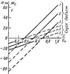
Rice. 2. Dependencies of the torque of the electric drive on the load of the car, the elevator, when the latter is on the first floor (1), in the middle of the shaft (2) and on the last floor (3).
An example. According to the technical data of a high-speed passenger elevator, determine the static moments on the motor shaft in different operating modes.
Given:
• maximum load capacity Gn = = 4900 N;
• movement speed v = 1 m / s;
• lifting height H = = 43 m;
• cabin weight G0 = 6860 N;
• counterweight weight Gnp = 9310 N;
• diameter of the traction beam Dm = 0.95 m;
• transmission ratio of the winch gearbox i = 40;
• transmission efficiency, taking into account the cabin friction on the shaft guides η = 0.6;
• weight of the rope GKAH = 862 N.
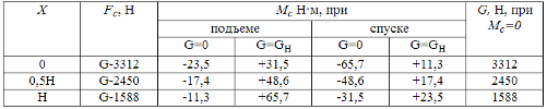
table 1
Tensile Strength:
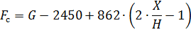
When the elevator system works up, when Fc > 0, the driving electric machine works in motor mode, and when Fc is 0, and in motor mode when Fc < 0.
The results of the calculation of the static moments according to the formula are summarized in a table. 1 and are shown in the graph of fig. 2.Note that more accurate calculations should take into account the resistance to the movement of the shaft guides, which is 5-15% of Fc.