Static loads on engines of main crane mechanisms
The power and torque of the motor shaft of the crane hoist in the static mode of lifting the load can be calculated by the formulas
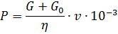
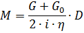
where P is the motor shaft power, kW; G is the force required to lift the load, N; G0 — lifting force of the gripping device, N; M is the motor shaft moment, Nm; v is the speed of lifting the load, m / s; D is the diameter of the towing winch drum, m; η — efficiency of the lifting mechanism; i is the gear ratio of the gearbox and chain hoist.
In the descent mode, the crane engine develops power equal to the difference between the friction power Ptr and the power due to the action of the weight of the descending load Pgr:
When lowering medium and heavy loads, energy is directed from the gear shaft to the motor because Pgr >> Ptr (brake release). In this case, the motor shaft power, kW, will be expressed by the formula

When lowering light loads or an empty hook, there may be cases where Pgr < Ptr.In this case, the engine works with a moment of movement (power descent) and develops power, kW,

Based on the given formulas, it is possible to determine the power of the crane motor at any load on the hook. When calculating, it should be remembered that the efficiency of the mechanism depends on its load (Fig. 1).
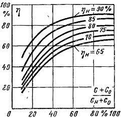
Rice. 1. Dependence of the efficiency of the mechanism on the load.
The power and torque on the shaft of the motors of the horizontal mechanisms of the movement of the crane in the static mode of operation can be determined by the formulas
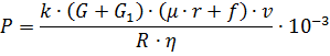
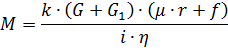
where P is the motor shaft power of the crane movement mechanism, kW; M is the motor shaft moment of the movement mechanism, Nm; G — weight of transported cargo, N; G1 — own weight of the movement mechanism, N; v — speed of movement, m / s; R is the radius of the wheel, m; r is the radius of the neck of the wheel axle, m; μ — coefficient of sliding friction (μ = 0.08-0.12); f — rolling friction coefficient, m (f = 0.0005 — 0.001 m); η — efficiency of the movement mechanism; k — coefficient accounting for the friction of the wheel flanges on the rails; i — gear ratio of the undercarriage reducer.
In a number of lifting and transport mechanisms, the movement does not take place in a horizontal direction. The effect of wind load, etc. is also possible. The formula for determining the power in this case can be represented as

Additionally marked: α — the angle of inclination of the guides to the horizontal plane; F — specific wind load, N / m2; S is the area on which the wind pressure acts at an angle of 90 °, m2.
In the last formula, the first term characterizes the motor shaft power required to overcome friction during horizontal movement; the second term corresponds to the lift force, the third is the power component from the wind load.
A number of cranes have a turntable on which the working equipment is located. The movement of the platform is transmitted through a gear wheel (turntable) with a diameter Dkp mounted on it. Between the platform and the fixed base there are rollers (rollers) with a diameter of dp. In this case, the power and torque of the crane motor due to frictional forces are found similarly to the case of reciprocating motion, namely:
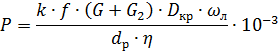
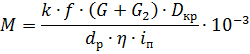
Here, in addition to the known values: G2 is the weight of the turntable with all the equipment on it, N; ωl — angular velocity, platforms, rad/sec; in — gear ratio of the swing mechanism gearbox and the drive gear of the transmission — turntable.
When determining the power of the crane electric drive, in some cases it is necessary to take into account the change in load when working on a slope. The wind load on the rotating mechanisms is determined by taking into account the difference in the wind forces acting on the load, the crane boom and the counterweight.
When designing electric drives for crane mechanisms, at the end of the motor selection, the electric drive is checked for permissible acceleration values, the data for which are given in table 1
Table 1 Name of the mechanisms and their purpose
The name of the mechanisms and their purpose Acceleration, m / s2 Lifting mechanisms intended for lifting liquid metals, fragile objects, products, various assembly works 0.1 Lifting mechanisms of parks of assembly and metallurgical workshops 0.2 — 0.5 Lifting mechanisms of gripping cranes 0.8 Mechanisms for movement of cranes intended for precision assembly work and transportation of liquid metals, fragile objects 0.1 - 0.2 Movement mechanisms with the force of attraction of gravity at full 0.2 - 0.7 Full Grip Crane Trolleys 0.8 — 1.4 Crane Swivels 0.5 — 1.2