Automated electric drive of crane mechanisms with thyristor control
 Modern systems of electric drives of crane mechanisms are mainly implemented using asynchronous motors, the speed of which is controlled by the relay-contactor method by introducing resistances into the rotor circuit. Such electric drives have a small speed control range and when starting and stopping create large kicks and accelerations, which adversely affects the performance of the crane structure, leads to swinging of the load and limits the use of such systems on cranes with increased height and lifting capacity .
The development of power semiconductor technology makes it possible to introduce fundamentally new solutions in the structure of the automated electric drive of crane installations. Currently, an adjustable electric drive with DC motors driven by powerful thyristor converters is used on the lifting and moving mechanisms of tower cranes and bridge cranes - TP system - D.
The motor speed in such systems is regulated in the range (20 ÷ 30): I by changing the armature voltage. At the same time, during transient processes, the system ensures that accelerations and kicks are obtained within the specified norms.
Good regulating qualities are also manifested in an asynchronous electric drive, when a thyristor converter is connected to the stator circuit of an asynchronous motor (AM). Changing the motor stator voltage in a closed ACS allows limiting the starting torque, achieving a smooth acceleration (deceleration) of the drive and the necessary speed control range.
The use of thyristor converters in the automated electric drive of crane mechanisms is increasingly used in domestic and foreign practice. In order to get acquainted with the principle of operation and the possibilities of such installations, let's briefly dwell on two variants of control schemes for DC and AC motors.
In fig. 1 shows a schematic diagram of thyristor control of an independently excited DC motor for a bridge crane lifting mechanism. The armature of the motor is fed by a reversible thyristor converter, which consists of a power transformer Tr, which serves to match the voltage of the converter and the load, two groups of thyristors T1 — T6 and T7 — , smoothing reactors 1UR and 2UR, which are both smoothing reactors made unsaturated.
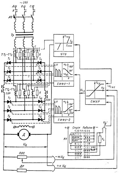
Rice. 1. Scheme of the electric drive of the crane according to the TP-D system.
The group of thyristors T1 — T6 works as a rectifier when lifting and an inverter when lowering heavy loads, since the direction of current in the armature circuit of the motor for these modes is the same. The second group of thyristors T7 — T12, providing the opposite direction of the armature current, works as a rectifier during power down and in transient modes of starting the motor for lowering the brakes, as an inverter when stopping in the process of lifting loads or hook.
Unlike mechanisms for moving cranes, where thyristor groups must be the same, for lifting mechanisms, the power of thyristors of the second group can be taken less than the first, since the motor current during power down is very less than when lifting and lowering heavy loads.
Regulation of the rectified voltage of the thyristor converter (TC) is carried out using a semiconductor pulse-phase control system consisting of two blocks SIFU-1 and SIFU-2 (Fig. 1), each of which supplies two firing pulses to the corresponding thyristor offset by 60 °.
To simplify the control system and increase the reliability of the electric drive, this scheme uses the coordinated control of the reversible TP. For this, the management characteristics and management systems of the two groups must be tightly linked. If the unlocking pulses are supplied to thyristors T1 — T6, providing the corrective mode of operation of this group, then the unlocking pulses are supplied to thyristors T7 — T12 so that this group is prepared for operation by the inverter.
The control angles α1 and α2 for any operating modes of the TP must be changed in such a way that the average voltage of the rectifier group does not exceed the voltage of the inverter group, i.e. if this condition is not met, then the rectified equalizing current will flow between the two groups of thyristors, which additionally loads the valves and transformer and can also cause tripping of the protection.
However, even with the correct matching of the control angles α1 and α2 from the thyristors of the rectifier and inverter groups, the flow of an alternating equalizing current is possible due to the inequality of the instantaneous values \u200b\u200bof the voltages UαB and UαI. To limit this equalization current, equalizing reactors 1UR and 2UR are used.
The armature current of the motor always passes through one of the reactors, due to which the ripples of this current are reduced, and the reactor itself is partially saturated. The second reactor, through which only equalizing current currently flows, remains unsaturated and limits iyp.
The thyristor electric crane drive has a single-loop control system (CS) made using a high-speed reversible summing magnetic amplifier SMUR, which is fed by a rectangular voltage generator with a frequency of 1000 Hz. In the presence of a power failure, such a control system allows obtaining satisfactory static characteristics and high quality of transient processes.
The electric drive control system contains negative feedback for the intermittent motor voltage and current, as well as a weak positive feedback for the voltage Ud.The signal in the circuit of the SMUR drive coils is determined by the difference between the reference voltage Uc coming from the resistor R4 and the feedback voltage αUd taken from the POS potentiometer. The value and polarity of the command signal, which determines the speed and direction of rotation of the drive, is regulated by the KK controller.
The reverse voltage Ud is cut off using silicon zener diodes connected in parallel with the SMUR main windings. If the voltage difference Ud — aUd is greater than Ust.n, then the zener diodes conduct current and the voltage of the control coils becomes equal to Uz.max = Ust.n.
From this point on, the change in the signal aUd to decrease does not affect the current in the main windings of the SMUR, i.e. the negative feedback for the voltage Ud does not work, which usually happens at motor currents Id> (1.5 ÷ 1.8) Id .n.
If the feedback signal aUd approaches the reference signal Uz, then the voltage on the zener diodes becomes less than Ust.n and the current does not flow through them. The current in the main windings of the SMUR will be determined by the voltage difference U3 — aUd and in this case the negative voltage feedback comes into play.
The negative current feedback signal is taken from two groups of current transformers TT1 — TT3 and TT4 — TT8, working with groups of thyristors T1 — T6 and T7 — T12, respectively. In the BTO current interrupter, the three-phase alternating voltage U2TT ≡ Id obtained on the resistors R is rectified, and through the zener diodes, which act as a reference voltage, the signal Uto.s is fed to the current windings of the SMUR, lowering the resulting result at the input of the amplifier.This reduces the converter voltage Ud and limits the armature circuit current Id in static and dynamic modes.
In order to obtain a high fill factor of the mechanical characteristics ω = f (M) of the electric drive and to maintain a constant acceleration (deceleration) in transient modes, in addition to the connections listed above, a positive feedback is applied in the circuit by tension.
The gain factor of this connection is chosen kpn = 1 / kpr ≈ ΔUy / ΔUd. in accordance with the initial section of the characteristic Ud = f (Uy) of the converter, but with an order smaller than the coefficient α of the negative feedback on Ud. The effect of this relationship is mainly manifested in the present discontinuity zone, providing steeply dipping sections of the feature.
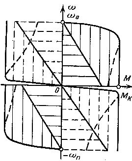
In fig. 2, a shows the static characteristics of the hoist drive for different values of the reference voltage U3 corresponding to different positions of the controller.
As a first approximation, it can be assumed that in the transition modes of start, reverse and stop, the operating point in the coordinate axes ω = f (M) moves along the static characteristic. Then the acceleration of the system:
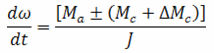
where ω is the angular velocity, Ma is the moment developed by the motor, Mc is the moment of resistance of the moving load, ΔMc is the moment of losses in the gears, J is the moment of inertia reduced to the motor shaft.
If we ignore transmission losses, then the condition for the equality of acceleration when starting the engine up and down, as well as when stopping from up and down is the equality of the dynamic moments of the electric drive, that is, Mdin.p = Mdin.s.To fulfill this condition, the static characteristics of the hoist drive must be asymmetric with respect to the speed axis (Mstop.p> Mstop.s) and have a steep front in the region of the braking moment value (Fig. 2, a).
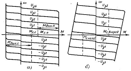
Rice. 2. Mechanical characteristics of the electric drive according to the TP-D system: a — lifting mechanism, b — movement mechanism.
For the drives of crane travel mechanisms, the reactive nature of the resistance moment, which does not depend on the direction of travel, must be taken into account. At the same value of motor torque, the reactive resistance torque will slow down the starting process and speed up the stopping process of the drive.
To eliminate this phenomenon, which can lead to slippage of the driving wheels and rapid wear of mechanical transmissions, it is necessary to maintain approximately constant accelerations during starting, reversing and stopping in the driving mechanisms. This is achieved by obtaining the static characteristics ω = f (M) shown in Fig. 2, b.
The specified types of mechanical characteristics of the electric drive can be obtained by correspondingly varying the coefficients of negative current feedback Id and positive voltage feedback Ud.
The complete control scheme of the thyristor controlled electric drive of the overhead crane includes all interlocking connections and protection circuits which are discussed in the diagrams given earlier.
When using TP in the electric drive of crane mechanisms, attention should be paid to their power supply.The significant non-sinusoidal nature of the current consumed by the converters causes distortion of the voltage waveform at the input of the converter. These distortions affect the operation of the converter power section and the pulse phase control (SPPC) system. Distortion of the line voltage waveform causes significant underutilization of the motor.
Supply voltage distortion has a strong effect on SPPD, especially in the absence of input filters. In some cases, these distortions can cause the thyristors to randomly open fully. This phenomenon can best be eliminated by feeding the SPPHU from separate carts connected to a transformer that does not have a rectifier load.
The possible ways of using thyristors to control the speed of asynchronous motors are very diverse — these are thyristor frequency converters (autonomous inverters), thyristor voltage regulators included in the stator circuit, impulse regulators of resistance and currents in electrical circuits, etc. .
In crane electric drives, thyristor voltage regulators and pulse regulators are mainly used, which is due to their relative simplicity and reliability. However, the use of each of these regulators separately does not fully meet the requirements for electric drives of crane mechanisms.
In fact, when only a pulse resistance regulator is used in the rotor circuit of an induction motor, it is possible to provide a regulation zone limited by natural and corresponding to the mechanical characteristics of the impedance rheostat, i.e.the adjustment zone corresponds to the motor mode and the opposition mode with incomplete filling I and IV or III and II quadrants of the plane of mechanical characteristics.
The use of a thyristor voltage regulator, especially a reversible one, basically provides a speed control zone covering the entire working part of the plane M, ω from -ωn to + ωn and from — Mk to + Mk. However, in this case, there will be significant slip losses in the engine itself, which leads to the need to significantly overestimate its installed power and, accordingly, its dimensions.
In this connection, asynchronous electric drive systems for crane mechanisms are created, where the motor is controlled by a combination of pulsed regulation of the resistance in the rotor and changes in the voltage supplied to the stator. This fills in the four quadrants of mechanical performance.
A schematic diagram of such a combined control is shown in Fig. 3. The rotor circuit includes a resistance pulse control circuit in the rectified current circuit. The parameters of the circuit are selected to ensure the operation of the motor in the I and III quadrants in the areas between the rheostat and the natural characteristics (in Fig. 4, shaded with vertical lines).
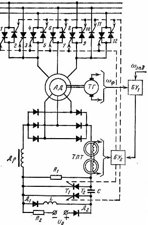
Rice. 3. Diagram of a crane electric drive with a thyristor regulator of the stator voltage and impulse control of the rotor resistance.
In order to control the speed in the areas between the rheostat characteristics and the speed axis shaded by horizontal lines in fig. 4, as well as for reversing the motor, a thyristor voltage regulator is used, consisting of pairs of anti-parallel thyristors 1—2, 4—5, 6—7, 8—9, 11—12.Changing the voltage supplied to the stator is carried out by adjusting the opening angle of thyristor pairs 1-2, 6-7, 11-12-for one direction of rotation and 4-5, 6-7, 8-9-for other direction of rotation.
Rice. 4. Rules for combined control of an induction motor.
To obtain rigid mechanical characteristics and to limit motor torques, the circuit provides speed and rectified rotor current feedback provided by a TG tachogenerator and a DC transformer (magnetic amplifier) TPT
It is easier to fill the entire I quadrant by connecting a capacitor with resistance R1 in series (Fig. 3). In this case, the equivalent resistance in the rectified rotor current can vary from zero to infinity and thus the rotor current can be controlled from the maximum value to zero.
The range of motor speed regulation in such a scheme extends to the ordinate axis, but the capacitor capacitance value turns out to be very significant.
To fill the entire I quadrant at lower capacitance values, the resistance of the resistor R1 is divided into separate steps. In the first stage, capacitance is successively introduced, which is switched on at low currents. The steps are removed by a pulse method, followed by a short circuit of each of them through thyristors or contactors. Filling the entire I quadrant can also be obtained by combining pulsed changes in resistance with pulsed operation of the motor. Such a scheme is shown in fig. 5.
In the area between the speed axis and the characteristic of the rheostat (Fig. 4), the motor operates in pulse mode.At the same time, control pulses are not supplied to the thyristor T3 and it remains closed all the time. The circuit that realizes the pulse mode of the motor consists of a working thyristor T1, an auxiliary thyristor T2, a switching capacitor C and resistors R1 and R2. When thyristor T1 is open, current flows through resistor R1. Capacitor C is charged to a voltage equal to the voltage drop across R1.
When a control pulse is applied to thyristor T2, the capacitor voltage is applied in the opposite direction to thyristor T1 and closes it. At the same time, the capacitor is being recharged. The presence of motor inductance leads to the fact that the process of recharging the capacitor is of an oscillatory nature, as a result of which thyristor T2 closes on its own without giving control signals, and the rotor circuit turns out to be open. Then a control pulse is applied to the thyristor T1 and all processes are repeated again.
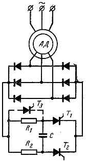
Rice. 5. Scheme of impulse combined control of an asynchronous motor
Thus, with the periodic supply of control signals to the thyristors, for some part of the period, a current flows in the rotor, determined by the resistance of the resistor R1. In the other part of the period, the rotor circuit turns out to be open, the torque developed by the motor is zero, and its operating point is on the speed axis. By changing the relative duration of the thyristor T1 during the period, it is possible to obtain the average value of the torque developed by the motor from zero to the maximum value corresponding to the operation of the rheostat characteristic when the rotor R1 is introduced into the circuit
By using various feedbacks, it is possible to obtain characteristics of the desired type in the region between the speed axis and the rheostat characteristic. The transition to the region between the rheostat and the natural characteristics requires thyristor T2 to remain closed at all times and thyristor T1 to remain open at all times. By short-circuiting the resistance R1 using a switch with the main thyristor T3, it is possible to smoothly change the resistance in the rotor circuit from the value R1 to 0, thus providing a natural characteristic of the motor.
The impulse mode of the commutated motor in the rotor circuit can also be performed in dynamic braking mode. By using different feedbacks, in this case, in the II quadrant, the desired mechanical characteristics can be obtained. With the help of the logic control scheme, it is possible to perform an automatic transition of the engine from one mode to another and to fill all quadrants of the mechanical characteristics.