Choice of electric drive for conveyors
 Despite the significant design diversity of conveyors, when choosing an electric drive, they can be combined into one characteristic group. First of all, it should be noted that due to technological conditions, these mechanisms usually do not require speed control.
Only a few conveyors use a shallow speed control in the 2:1 range to change the speed of operation. Conveyor motors operate under various environmental conditions, in many cases in dusty, humid rooms with high or low temperatures, outdoors, in workshops with aggressive environments, etc.
A characteristic feature of conveyors is the large static moment of resistance at rest, which, as a rule, exceeds the nominal due to various reasons, including solidification of the lubricant in rubbing parts. Thus, requirements for high reliability, ease of maintenance, as well as provision of increased starting torque are imposed on the electric drive of conveyors.
In some cases, additional requirements arise to ensure a smooth start, prevent belt slippage, small speed control and coordinated rotation of several electric drives. All these requirements are adequately met by squirrel-cage or phase-rotor induction motors.
The power selection of the conveyor drive motor is done by a gradual convergence method together with the calculation and selection of all the mechanical equipment. The first stage of the calculation consists in the approximate determination of the traction effort and tension, according to which the preliminary selection of the engine power and the choice of mechanical equipment is made. At the second stage of the calculation, an updated graph of the tension dependence is built, taking into account losses along the length of the conveyor. After drawing the graph, the places for mounting the electric drive are selected, the motor and mechanical equipment are checked against the resulting force and voltage.
A large number of formulas are known for approximately determining the traction effort and tension of the conveyor, proposed on the basis of experience in the design and operation of conveyors. One of them looks like this:
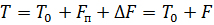
where T is the conveyor voltage, N; F is the effort that the electric motor must overcome, N; T0 — prestress, N; Fп is the effort due to lifting the load, N; ΔF is the total force caused by frictional forces on sections of the conveyor track, N.
According to the effort and tension in the traction element of the conveyor, a preliminary selection of the motor and mechanical equipment is made.Formulas for calculating losses in drums, gears, blocks and other equipment elements can be found in special literature on the mechanical part of conveyors.
To construct a traction force diagram, a conveyor path is drawn with all ups and downs, bends, drive and tension stations, guide blocks and drums. Then, if we proceed from the least loaded section of the conveyor, the losses in each element are taken into account and the tension of the traction element along the entire length is obtained. In fig. 1 shows diagrams of the traction forces of belt and chain conveyors with a single motor electric drive.
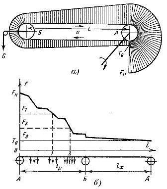
Rice. 1. Diagram of traction forces in belt (a) and chain (b) conveyors: a — drive station; b — voltage station.
The power of the conveyor drive motor is determined by the formula
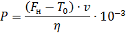
here P — engine power, kW; FH — force on the upcoming section of the traction element, N; v is the speed of movement of the traction element, m / s; η — drive mechanism efficiency.
In the design of belt conveyors, after plotting a traction force diagram, the location of the drive station on the conveyor track is determined. Electric drive of long conveyors, for example large flow conveying systems, is impractical to do with a single motor, since in this case considerable effort is put into the mechanical equipment located near the drive station.
The overloading of the specified sections of the conveyor leads to the fact that the dimensions of the mechanical part and especially of the traction element increase sharply.To prevent the occurrence of large traction forces, the conveyors are driven by several drive stations. In this case, a force is generated in the traction element of the drive station that is proportional to the static resistance of only one section, and the traction element does not transfer forces to drive the entire conveyor.
If there are several drive stations on the belt conveyor, the location of their installation is selected according to the traction force diagram, so that the traction force of the motors of several stations is approximately equal to the force of a single-motor electric drive (Fig. 2).
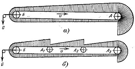
Rice. 2. Scheme of the pulling forces of a belt conveyor: a — with a single-motor electric drive; b — with multi-motor electric drive.
However, it should be taken into account that for the final selection of the motor power of the drive station, it is necessary to build an updated diagram of traction forces for each branch. This refinement is due to the fact that the sum of the efforts of all sections may not be equal to the force with a single-motor drive, which is determined by a reduction in the section of the traction element and a corresponding reduction in friction losses with a multi-motor drive.
Note that for large belt conveyors, where the motor power reaches tens and hundreds of kilowatts, the route length between the drive stations is most often about 100-200 m. It should be noted that the structural integration of the drive stations in the conveyor is associated with certain difficulties, especially for belt conveyors ... Therefore, the most convenient places for their installation are the end points of the route.In some enterprises, the length of non-sectioned conveyors reaches 1000-1500 m.
The installation of several drive stations on a belt conveyor leads, as a rule, to an increase in the performance of a multi-motor electric drive compared to a single one. This is determined by the fact that, for example, when starting a conveyor, an engine can run at idle speed.
As the load increases, the second motor is turned on, and then the following ones. If the load is reduced, the motors can be partially switched off. These switches lead to a reduction in the running time of the engines at low load and an increase in their performance. In case of blockage of conveyors by transported materials, increase of static moment due to solidification of lubricant, etc., it is possible to start all motors together to create increased starting torque.
Of great importance when choosing a system for controlling the electric drive of belt conveyors is the correct calculation of the elastic deformations of the traction element and the accelerations that may occur during transient processes. Let us turn to fig. 3, which shows the graphs of the speed change at the start of the engine of the upcoming 1 and the expiration of 2 branches of the strip. The conveyor is driven by an induction squirrel-cage motor, the static torque of the motor shaft is assumed to be constant.
The nature of the change in speed in branches 1 and 2 of the conveyor will largely depend on the length of the belt. For a small length of the conveyors, about a few tens of meters, the graphs of changes in the speed of branches 1 and 2 over time will be close to each other another (Fig. 3, a). Naturally, in this case, branch 2 will start to move with some lag relative to branch 1 due to elastic deformation of the strip, but the speeds of the branches level off quite quickly, albeit with some fluctuations.
The situation is slightly different when running conveyors with long belts, about hundreds of meters. In this case, the start from the location of the outgoing branch 2 of the conveyor can begin after the drive motor reaches a constant speed (Fig. 3, b). On long belt conveyors, a delay can be observed in the beginning of the movement of the belt sections at a distance of 70-100 m from the inbound branch at a constant engine speed. In this case, additional elastic tension is created in the belt and the traction force is applied to the following sections of the belt with a kick.
As all sections of the conveyor reach a steady speed, the elastic tension of the belt decreases. The return of the stored energy can lead to an increase in the speed of the belt compared to the stationary one and to its oscillations (Fig. 3, b). Such a transient nature of the traction element is extremely undesirable, as it leads to increased wear of the belt, and in some cases to tearing.
These circumstances lead to the fact that due to the nature of the start-up and other transient processes in the electric drive of belt conveyors, strict requirements are set to limit the acceleration of the system. Their satisfaction leads to a certain complication of the electric drive: multi-level control panels for asynchronous motors with a phase rotor, additional load, starting devices, etc. appear.
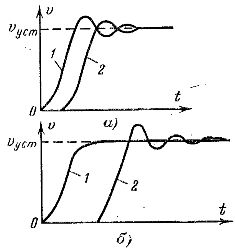
Rice. 3. Velocity diagrams of various sections of the belt conveyor at startup.
The simplest way to limit acceleration in the electric drive of belt conveyors at start-up is rheostat control (Fig. 4, a). The transition from one starting characteristic to another ensures a smooth acceleration of the system. A similar solution to the problem is often used on belt conveyors, but leads to a significant increase in the size of control panels and starting rheostats.
In some cases, it is more expedient to limit the acceleration of the electric drive system by additional braking of the motor shaft during start-up, since the creation of additional braking torque MT reduces the dynamic torque (Fig. 4, b). As can be seen from the graphs, the acceleration of the system is artificially reduced due to deceleration, as a result of which the speed fluctuations in the inlet and outlet branches of the conveyor are reduced. At the end of the start, the source of the additional braking torque must be disconnected from the motor shaft.
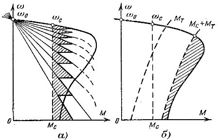
Rice. 4. To the methods of starting belt conveyors.
Let us note in passing that the limitation of accelerations in the electric drive system can be achieved by using both methods at the same time, for example, the rheostat starts by connecting a source of additional braking torque. This method is used on long single-section conveyors where the cost of the belt determines the majority of the capital cost of the entire plant.
The smooth start of the system with the creation of an artificial load on the shaft is practically carried out using conventional shoe brakes with electric or hydraulic control, connecting induction or friction clutches to the motor shaft, using additional braking machines, etc. the stator circuit.
We also note that the problem of limiting accelerations in the conveyor belt can be achieved in other ways, for example, using a two-motor rotary stator drive system, a multi-speed squirrel-cage motor system, an asynchronous electric drive with thyristor control in the motor rotor circuit and others.
It should be noted that the drive motor for chain conveyors should be located, as a rule, after the section with the greatest load, ie. the section of the route with a large amount of loads and steep climbs and turns.
Usually, based on this recommendation, the engine is positioned at the highest lift point. When installing the drive, take into account that the sections of the track with a large number of bends should have as little tension as possible: this leads to a reduction of losses on the curved part of the track.
Determination of the power of the drive motor of the chain conveyor is also carried out on the basis of drawing the diagram of the traction force along the entire route (see Fig. 1, b).
Knowing in accordance with the diagram the tension and force on the upcoming section of the traction element, as well as the speed of movement, the power of the electric drive can be calculated by the formula.
Chain conveyors, despite the considerable length of the routes, due to the relatively low speeds, for example in machine-building enterprises, most often work with one drive motor with a relatively low power (a few kilowatts). In the same plants, however, there are more powerful conveyor installations with chain traction units where several drive motors are used. This electric drive system has a number of distinctive features.
In a multi-motor chain conveyor drive, the rotors of the motors at equilibrium will have the same speed because they are mechanically connected through the traction element. In transient modes, the rotor speeds may differ slightly due to the elastic deformations of the traction element.
Due to the presence of a mechanical connection between the rotors of the machines of a multi-motor conveyor, additional stresses arise in the traction element, due to different loads on the branches. The nature of these stresses can be elucidated by considering the pipeline diagram shown in Fig. 5. With the same load on the conveyor splitters, all four motors, if their characteristics are the same, will have the same speed and load.
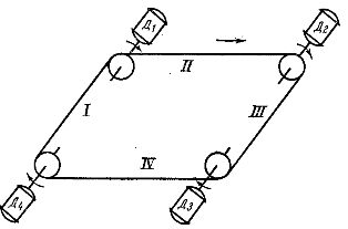
Rice. 5. Scheme of a multi-motor conveyor.
An increase in the load on branch I will lead to the fact that, first of all, the speed of motor D1 will decrease, and the speed of motors D2, D3 and D4 will remain constant. Thus, motor D2 will rotate at a speed greater than that of motor D1 and will create an additional voltage in branches II and then I.
The voltage on branch II will cause some unloading of motor D1 and increase its speed. The same picture will happen in branch II as motor D3 will take part of the load from branch II of the conveyor. Gradually, the speeds and loads of the engines equalize, but additional stress is created in the traction element.
When choosing a multi-motor chain drive, the traction force diagram is plotted in the same way as for a single motor. The electric drive must provide the maximum traction force that is necessary to overcome the resistance to the movement of the conveyor. In fig. 1, b shows a diagram of the traction forces in the traction element of the conveyor, according to which it is possible to outline the place of installation of the drive stations.
If, for example, we set the condition that the number of drive stations is three and all engines must provide the same traction force, then the engines must be installed at a location characterized by point 0 and at a distance 0 -1 and 0-2 from it, respectively (Fig. 6, a). During the operation of the conveyor, in the case of complete matching of the mechanical characteristics of the motors, each of them creates approximately the same traction force (Fn — T0) / 3.
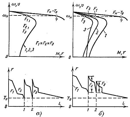
Rice. 6. Graphs of load distribution in the traction element of the chain conveyor.
The use of multi-motor drives on chain conveyors significantly reduces the load on the traction element, as a result of which the mechanical equipment can be selected more lightly. The optimal number of drive stations on the conveyor is selected through a technical and economic comparison of the options, which takes into account both the cost of the electric drive and the mechanical equipment.
In the case that the characteristics of the engines are slightly different, each machine can create a thrust effort that differs from the calculated one. In fig. 6a shows the mechanical characteristics of three engines of the same power, with the same parameters, and in fig. 6, b — characteristics of engines with different parameters. The forces that the engines will create are found by building common characteristic 4.
Since the rotors of all conveyor motors are firmly connected to the traction element, their speed corresponds to the speed of the chain, and the total force is equal to (Fa — T0). The thrust of each engine can be easily obtained by drawing a horizontal line corresponding to the rated speed and crossing characteristics 1, 2, 3 and 4.
In fig. 6, a and b, in addition to the mechanical characteristics of the engines, traction force diagrams are shown. In the traction element, with different characteristics of the motors, additional tension can be created due to the difference in the traction forces developed by the conveyor motors.
When choosing the motors of the conveyor drive stations, their characteristics should be checked and, if possible, a complete match should be achieved.Based on these conditions, it is advisable to use asynchronous motors with a wound rotor, where the matching of characteristics can be achieved by introducing additional resistances in the rotor circuit.
In fig. 7 shows the mechanical characteristics of the two-motor electric conveyor drive. Characteristics 1 and 2 are natural, respectively characteristics 1 'and 2' are obtained with additional resistance introduced in the rotor circuit of the motor. The total torque and traction force developed by the engines will be the same for both hard 1, 2 and soft 1', 2' characteristics. However, the load between the engines is distributed more favorably with soft characteristics.
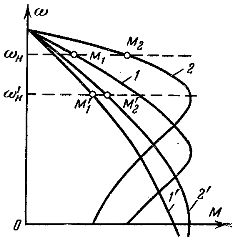
Rice. 7. Load distribution between the conveyor motors with different stiffness of their characteristics.
When designing mechanical equipment, it should be taken into account that the speed of the conveyor decreases with the softening of the characteristics of the motors, and in order to maintain a constant nominal speed of the conveyor, it is necessary to change the gear ratio of the gearboxes. In practice, it is advisable to introduce additional resistance in the rotor circuit of conveyor motors with no more than 30% of the nominal resistance of the rotor. In this case, the engine power should increase approximately 1 / (1 —s) times. When squirrel-cage asynchronous motors are installed on the conveyor, they should be selected with increased slip.