Diagram of the electric drive of the lifting mechanism of the crane with the TSDI panel
 The electric drive of the crane with a magnetic controller of the TSDI type, fig. 1, provides dynamic braking of a self-excited induction motor during descent and impulse switch control during ascent. Electric drives with dynamic braking with self-excitation are implemented only for lifting mechanisms in order to obtain solid braking characteristics during descent (Fig. 2), which makes it possible to increase the range of speed regulation to a value of 8: 1. Using of impulse switch control a rigid characteristic is obtained in the first position during lifting, which also increases the control range to (6 … 4): 1.
Reversing is carried out through contactors KM1V KM2V, dynamic braking — through contactor KM2. To increase the reliability of the electric drive in the self-excited dynamic braking mode, an initial bias is used.The motor is supplied with direct current at initial deviation from the network through the contacts of the contactor KM4, resistance R1, diode VI, relay coil KA2, contactor contact KM2. Contacts KM2 also connect two phases of the motor to the rectifier UZ1. Speed regulation is carried out by contactors KM1V … KM4V.
Rigid characteristics in self-excited dynamic braking are obtained due to a change in the DC current supplying the stator winding when the load changes. The ICR pulse switch adjustment unit includes thyristors VSI ... VS3, a pulse shaper of resistors R2 ... R4, a measuring bridge UZ2 connected to the rotor circuit through capacitors C1 with an output to resistors R7, R8, zener diodes VD1 and VD2 ... The circuit uses semiconductor time relays KT2 ... KT4, conventionally shown in the control block circuit.
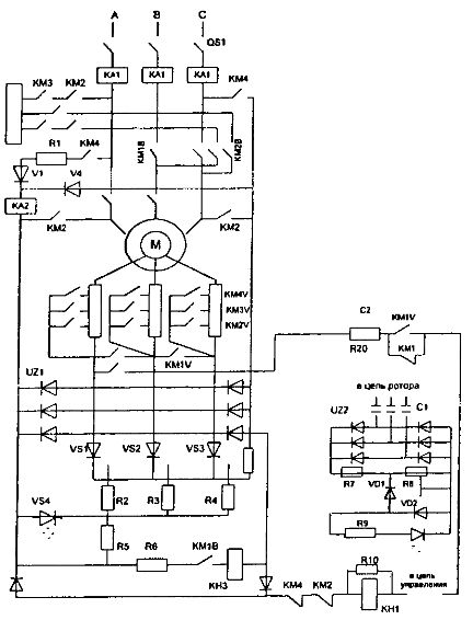
Fig. 1. Diagram of the electric drive of the lifting mechanism of the crane with the TSDI panel
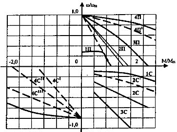
Fig. 2. Mechanical characteristics of the crane electric drive under control of the TSDI panel
Control is provided by the controller, which has four fixed positions in each direction of travel. The chain is asymmetric. Speed regulation in the upward direction is carried out by changing the resistance of the resistor stages in the rotor circuit under the control of the time relay KT2 ... KT4. In the first position of the controller, contactor KM1 is open and all resistors on the AC side and resistors R11 on the DC side are connected to the rotor circuit.
A semi-regulated bridge consisting of thyristors VS1 … VS3 and diodes UZ1 serves to correct the voltage.When the voltage is greater than the breakdown of the zener diode VD1, the current flows through the optocoupler VS4 and the thyristors VS1 ... VS3 open, the motor operates according to the impedance characteristic. When the voltage on the zener diode VD1 drops below its nominal value, the current does not flow through the optocoupler and the thyristors close. As the EMF speed decreases, the rotor rises and the thyristors open.
This control chain operation allows you to create a rigid mechanical characteristic 1P. In the second position, the KM IV contactor is turned on and bypasses the rectifier circuit, the motor switches to the 2P characteristic, etc.
The dynamic braking mode is applied in all descent positions, except for the last one, where the motor is powered by the mains, and the descent is carried out in regenerative braking mode. The disadvantage of the scheme is the inability to reduce light loads at low speed, as well as the lack of transition from braking to motor mode in the 1st ... 3rd position of descent.
The indicated shortcomings are eliminated by the P6502 control panels, designed to control asynchronous motors with a phase rotor in multi-motor electric drives of mechanisms for lifting and moving cranes. The electric drive of the mechanism contains a set of two drive motors, with a total power of up to 125 kW.
In crane electric drives, adjustment of mechanical characteristics with synchronous rotational speeds and automatic transition from I to II square (from III to IV) and vice versa are obtained by adding the mechanical characteristics of one motor, by transferring it from the motor operation mode to the dynamic stop mode during each semi-periodic power network, which is carried out according to a special power scheme for the stator windings of the electric motor (Fig. 3) with 2 electric motors.
The scheme allows simultaneous powering of electric motors with direct and alternating current. A three-phase alternating voltage is supplied to the beginning of the windings of the electric motor from the thyristor voltage regulator TRN and to the ends of the windings of any two electric motors connected in two stars (two phase windings of one motor and the third phase windings of another motor are combined with a star) — DC voltage.
The DC voltage is supplied by the rectifier bridge UZ3, fed by the transformer T, whose primary winding of each phase shunts the phase TPH. The rms magnitude of the AC and DC voltage applied to the motor is a function of the conduction angle of the thyristors.
Each point of the mechanical characteristic of the drive is obtained by algebraically adding two moments: the torque developed by the electric motor in motor mode and the torque developed by the motor in dynamic braking mode with independent excitation.
When the thyristors are fully open, there is no dynamic braking.The presence of speed feedback (using a tachogenerator) ensures that the rigid control characteristics shown in Fig. 4. Range of speed adjustment up to 8: 1.
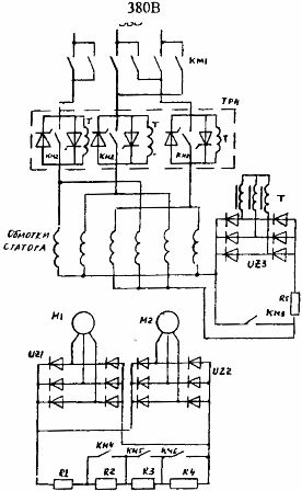
Fig. 3. Simplified power circuit of the crane electric drive with control panels P6502
The simultaneous inclusion of all drive motors from one mechanism and the uniform distribution of the load between them is ensured by the fact that the switching in the stator and rotor circuits is carried out by single switching devices, for which the rotor windings of the electric motors are connected to a common resistor for starting regulation through three-phase rectifier bridges UZ1 and UZ2. To control the TRN thyristors, low-power magnetic amplifiers of the TUM type (A1 … A3) are used (not shown in the diagram).
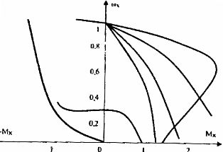
Fig. 4. Mechanical characteristics of the electric drive of the crane made in fig. 3 in the 1st and 2nd quadrants