Anti-aliasing filters and voltage stabilizers
 Smoothing filters are designed to reduce rectified voltage ripple. Ripple smoothing is evaluated by the smoothing factor q.
The main elements of smoothing filters are capacitors, inductors and transistors whose resistance is different for direct and alternating currents.
Depending on the type of filter element, a distinction is made between capacitive, inductive and electronic filters. According to the number of filtering links, filters are divided into single-link and multi-link.
A capacitive filter is a capacitor with a large capacity that is connected in parallel with the load resistor Rn. A capacitor has high DC resistance and low AC resistance. Let's consider the operation of the filter on the example of a half-wave rectifier circuit (Fig. 1, a).
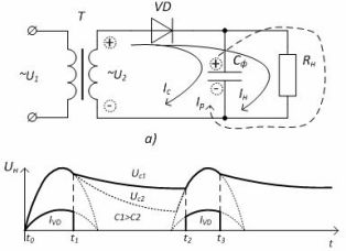
Figure 1-Single-phase half-wave rectifier with capacitive filter: a) circuit b) timing diagrams of operation
When a positive half-wave flows in the time interval t0 — t1 (Fig. 2.63, b), the load current (diode current) and the capacitor charge current flow.The capacitor is charged and at time t1 the voltage in the capacitor exceeds the voltage drop of the secondary winding — the diode closes and in the time interval t1 — t2 the current in the load is provided by the discharge of the capacitor. Che. the current in the load flows constantly, which significantly reduces the ripple of the rectified voltage.
The larger the capacitance of the capacitor Cf, the smaller the excitation. This is determined by the discharge time of the capacitor — the discharge time constant τ = СfRн. At τ> 10, the smoothing coefficient is determined by the formula q = 2π fc m Cf Rn, where fc is the frequency of the network, m is the number of half-periods of the rectified voltage.
It is recommended to use a capacitive filter with a high resistance RH load resistor at low load powers.
Inductive filter (choke) is connected in series with Rn (Fig. 3, a). Inductance has low DC resistance and high AC resistance. Ripple smoothing is based on the phenomenon of self-induction, which initially prevents the current from increasing, and then supports it with its decrease (Fig. 2, b).
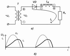
Figure 2-Single-phase half-wave rectifier with inductive filter: a) circuit, b) timing diagrams of operation
Inductive filters are used in rectifiers of medium and high power, that is, in rectifiers operating with large load currents.
The smoothing coefficient is determined by the formula: q = 2π fs m Lf / Rn
The operation of the capacitive and inductive filter is based on the fact that during the flow of the current consumed by the network, the capacitor and the inductor store energy, and when there is no current from the network, or it decreases, the elements give a shutdown of the stored energy, maintaining the current (the voltage ) in the load.
Multi-junction filters use the smoothing properties of both capacitors and inductors. In low-power rectifiers, where the resistance of the load resistor is several kOhm, instead of the choke Lf, the resistor Rf is included, which significantly reduces the mass and dimensions of the filter.
Figure 3 shows the types of LC and RC ladder filters.
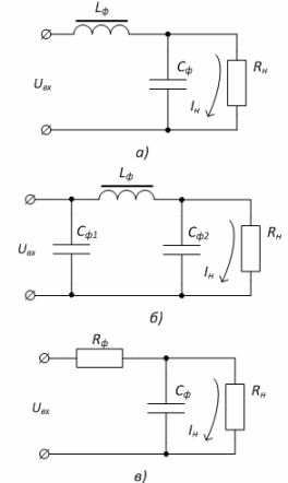
Figure 3-Multi-junction filters: a) L-shaped LC, b) U-shaped LC, c) RC-filter
Stabilizers are designed to stabilize a constant voltage (current) of the load during fluctuations in the mains voltage and changes in the current consumed by the load.
Stabilizers are divided into voltage and current stabilizers, as well as parametric and compensation ones. The stability of the output voltage is evaluated by the stabilization factor Kst.
Parametric stabilizer based on the use of an element with a non-linear characteristic - a semiconductor zener diode. The voltage of the zener diode is almost constant with a significant change in the reverse current through the device.
The parametric stabilizer circuit is shown in Figure 4. The input voltage UBX is distributed between the limiting resistor Rlim and the parallel-connected zener diode VD and the load resistor Rn.

Figure 4 — Parametric stabilizer
As the input voltage increases, the current through the zener diode will increase, which means that the current through the limiting resistor will increase and a larger voltage drop will occur across it, and the load voltage will remain unchanged.
The parametric stabilizer has a Kst of the order of 20-50. The disadvantages of this type of stabilizers are low stabilization currents and low efficiency.
Parametric stabilizers are used as auxiliary voltage sources, as well as when the load current is small — no more than hundreds of milliamps.
A compensating stabilizer uses the variable resistance of the transistor as a limiting resistor. As the input voltage increases, the resistance of the transistor also increases, correspondingly, as the voltage decreases, the resistance decreases. In this case, the voltage in the load remains unchanged.
The stabilizer circuit of the transistors is shown in Figure 5. The principle of regulation of the output voltage URn is based on a change in the conductivity of the regulation transistor VT1.
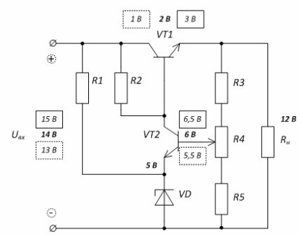
Figure 5 — Schematic of compensating voltage regulator
A voltage comparison circuit and a DC amplifier are assembled on the transistor VT2. The measuring circuit R3, R4, R5 is included in its base circuit, and the reference voltage source R1VD is included in the emitter circuit.
For example, as the input voltage increases, the output will also increase, which will lead to an increase in the voltage at the base of the transistor VT2, while at the same time the potential of the emitter VT2 will remain the same.This will lead to an increase in the base current, and hence the collector current of the transistor VT2 — the base potential of the transistor VT1 will decrease, the transistor will close and a larger voltage drop will occur on it, and the output voltage will remain unchanged.
Today, stabilizers are produced in the form of integrated circuits. A typical scheme for turning on an integrated stabilizer is shown in Figure 6.
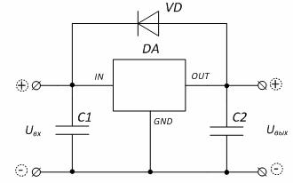
Figure 6 — Typical schematic for turning on a built-in voltage stabilizer
Designation of the outputs of the stabilizer microcircuit: «IN» — input, «OUT» — output, «GND» — common (case). If the stabilizer is adjustable, then there is an output «ADJ» — adjustment.
The selection of the stabilizer is based on the value of the output voltage, the maximum load current and the range of variation of the input voltage.