What is sequential driving
 The main purpose of servo drives: tracking the control signal entered into the system, changing according to a previously unknown law. Trackers make up a large group of drives used in industry. The most common case is the development of the movement of a particular input shaft from the output shaft of the drive. In this case, the repetition of the movement from the output shaft must be carried out with the necessary error. In servo drives, the controlled variable is usually the rotation angle Θ, and the regulation itself is position regulation.
The functional diagram of the servo drive shown in Fig. 1, has a closed structure with a rigid negative feedback for the rotation angle Θ2 output shafts.
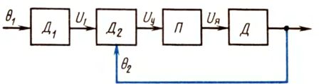
Rice. 1. Functional diagram of the sequential drive
The principle of the servo drive is as follows. Suppose that between the angle Θ1 input shaft and Θ2 of the output shaft a certain deviation appeared, i.e. Θ1 is not equal to Θ2.Sensors D1 and D2 generate voltages proportional to the angles of rotation and supply the control voltage Uy = U1-U2 to the input of the converter P, where U1 = k1Θ1, U2 = k2Θ2... Therefore, sensors D1 and D2 are usually called meter discrepancy... The converter P converts Uy to a proportional motor control signal, which can be the voltage applied to the armature.
The voltage Uy is formed in such a sign that the motor D, having received power, began to rotate its shaft in the direction in which the angle difference Θ2-Θ1 decreased. In other words, a sequential drive always strives to continuously automatically eliminate misalignment between the input and output shafts.
Potentiometric measuring instrument, selsin, working in transformer mode, rotary transformer, etc. are used as misalignment meter in servo drive, as a device converter — engine of the G -D system, EMU-D, MU-D, UV-D, etc.
A block diagram of the simplest servo system shown in Fig. 2, consists of selsyn of the SD sensor, selsyn of the SP receiver, which work in transformer mode and perform the functions of sensors D1 and D2, i.e., the input angle misalignment meter Θ1 and weekend Θ2.
Celsini — These are alternating current electric micromachines that are capable of self-synchronization. They are used in remote angle transmission systems such as sensors and receivers. The transfer of the angular value in such a system becomes synchronous, phased and smooth. In this case, there is only an electrical connection in the form of a communication line between the device that sets the angle (sensor) and the device that receives the transmitted value (receiver).
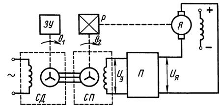
Rice. 2.Schematic of the servo drive with selsyns
Rice. 3. Selsin
The system includes a converter that rectifies the alternating voltage of the single-phase JV winding and amplifies it. The converter (see Fig. 2) must be sign-sensitive, that is, depending on the phase of the signal of the SP winding, it must supply a constant voltage with a positive or negative sign to the motor armature.
The executive motor is connected to the rotor of the joint venture through a reduction gear P. An input specifying the angle of rotation Θ1 is fed to the system by the main memory whose shaft is fixedly connected to the shaft of the SD. Sometimes this communication is done through a reducer.
If the charger moves the shaft SD from its initial position to the angle Θ1, an alternating voltage will appear at the output of the single-phase winding of the joint venture, the amplitude of which is proportional to the difference between the input and output angles of the drive Uy = U1 = k1(Θ1-Θ2 ).
The frequency of the voltage Uy is determined by the frequency of the supply of the single-phase winding of the LED (50, 400 Hz, etc.). The converter P rectifies and amplifies the voltage Uy.
In a schematic form, it can be represented by a phase-sensitive rectifier and a DC amplifier made on a different basis of elements. For example, a transistor amplifier can be used as a rectifier and an EMU can be used as an amplifier.
An electric motor that has received power in the form UI, depending on the polarity of this voltage, begins to rotate the shaft and the shaft of the joint venture through the gearbox in such a way that the difference in the angle Θ1 and Θ2 decreases.As soon as it turns out that Θ1-Θ2 = 0, the single-phase winding of the joint venture will stop producing voltage Uy, that is, Uy = 0. Then the voltage applied to the armature of the motor will be removed and it will stop rotating its shaft. In this way, the system responds to the control signal from the outside.
Often in servo systems, in addition to the negative feedback for the angle of rotation (position), feedback for the frequency of rotation is used. In this case, the scheme shown in fig. 2 will change.
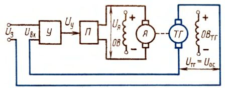
Rice. 4. Schematic of closed loop drive with negative velocity feedback
A tachogenerator will be placed on the motor shaft and the voltage from its winding will be fed to the converter P in series with the voltage Uy as shown in fig. 4. In practice, other types of feedback are also used.
You might be interested in this: What is an electric drive?