Parallel Excitation Motor Braking Modes
 The engine braking mode in the electric drive is used along with the engine. The use of an electric motor as an electric brake is widely used in practice to shorten the time of stopping and reversing, reduce the rotation speed, prevent the excessive increase of the travel speed and in a number of other cases.
The operation of the electric motor as an electric brake is based on the principle of reversibility of electric machines, that is, the electric motor under certain conditions switches to generator mode.
In practice, three modes are used for braking:
1) generator (regenerative) with energy return to the grid,
2) electrodynamic,
3) opposition.
When constructing mechanical characteristics in a rectangular coordinate system, it is important to determine the signs of the motor torque and rotational speed in the motor and braking modes. For this, the motor mode is usually taken as the main one, considering the rotational speed and torque of the motor in this mode as positive.In this regard, the characteristics n = f (M) of the motor mode are located in the first quadrant (Fig. 1). The location of the mechanical characteristics in the braking modes depends on the signs of the torque and the rotational speed.
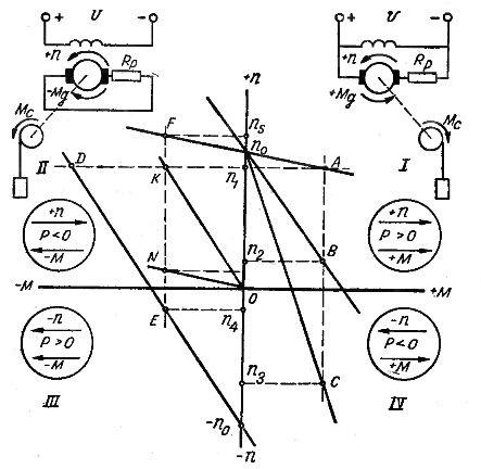
Rice. 1… Connection diagrams and mechanical characteristics of a parallel-excited motor in motor and brake modes.
Let us consider these modes and the corresponding sections of the mechanical characteristics of the parallel-excitation motor.
Opposition.
The state of the electric drive is determined by the combined action of the motor torque Md and the static load torque Mc. For example, the steady-state rotation speed n1 when lifting a load with a winch, it corresponds to the operation of the engine in a natural characteristic (Fig.1 point A) when Md = Ms. If additional resistance is introduced into the armature circuit of the motor, then the rotational speed will decrease due to the transition to the rheostat characteristic (point B corresponding to speed n2 and Md = Ms).
A further gradual increase in the additional resistance in the armature circuit of the motor (for example, to a value corresponding to the section n0Characteristics C) will first lead to the cessation of lifting the load, and then to a change in the direction of rotation, that is, the load will fall (point C). Such a regime is called opposition.
In the opposite mode, the moment Md has a positive sign. The sign of the rotational speed changed and became negative. Therefore, the mechanical characteristics of the opposition mode are found in the fourth quadrant, and the mode itself is generative.This follows from the accepted condition for determining the signs of torque and rotational speed.
In fact, the mechanical power is proportional to the product n and M, in motor mode it has a positive sign and is directed from the motor to the working machine. In the opposition mode, due to the negative sign of n and the positive sign of M, their product will be negative, therefore, mechanical power is transmitted in the opposite direction — from the working machine to the motor (generator mode). In fig. 1 characters n and M in motor and brake modes are shown in circles, arrows.
The sections of the mechanical characteristic corresponding to the oppositional mode are a natural extension of the characteristics of the motor mode from the first to the fourth quadrant.
From the considered example of switching the engine to the opposite mode, it can be seen that e. etc. c. the motor, depending on the speed of rotation, at the same time as the last one, when crossing the zero value, changes the sign and acts in accordance with the mains voltage: U = (-Д) +II amRfrom where I am II am = (U +E) / R
In order to limit the current, a significant resistance, usually equal to twice the starting resistance, is included in the armature circuit of the motor. The peculiarity of the opposition mode is that the mechanical power from the shaft side and the electrical energy from the network are supplied to the motor, and all this is spent on heating the armature: Pm+Re = EI + UI = Аз2(Ри + AZext)
The opposite mode can also be obtained by switching the windings in the opposite direction of rotation, while the armature continues to rotate in the same direction due to the reserve of kinetic energy (for example, when the machine with a reactive static moment - the fan stops).
In accordance with the accepted condition for reading signs n and M according to the motor mode, when switching the motor to reverse rotation, the positive directions of the coordinate axes should change, that is, the motor mode will now be in the third quadrant, and the opposition - in the second.
Thus, if the motor was operating in motor mode at point A, then at the moment of switching, when the speed has not yet changed, it will be with a new characteristic, in the second quadrant at point D. Stopping will occur down the characteristic DE (-n0), and if the engine is not turned off at speed t = 0, it will work on this characteristic at point E, rotating the machine (fan) in the opposite direction at speed -n4.
Electrodynamic braking mode
Electrodynamic braking is obtained by disconnecting the motor armature from the network and connecting it to a separate external resistance (Fig. 1, second quadrant). Obviously, this mode differs little from the operation of an independently excited DC generator. Work on a natural characteristic (direct n0) corresponds to the short-circuit mode, due to high currents, braking in this case is possible only at low speeds.
In the electrodynamic braking mode, the armature is disconnected from the U network, therefore: U = 0; ω0 = U / c = 0
The equation of mechanical characteristics has the form: ω = (-RM) / c2 or ω = (-Ri + Rext / 9.55se2) M
The mechanical characteristics of electrodynamic braking are through the source, which means that as the speed decreases, the engine braking torque decreases.
The slope of the characteristics is determined in the same way as in the motor mode, by the value of the resistance in the armature circuit.Electrodynamic braking is more economical than the opposite, since the energy consumed by the motor from the network is spent only on excitation.
The magnitude of the armature current and therefore the braking torque depends on the speed of rotation and the resistance of the armature circuit: I = -E/ R = -sω /R
Generator mode with energy return to the grid
This mode is only possible when the direction of action of the static torque coincides with the motor torque. Under the influence of two moments — the torque of the engine and the torque of the working machine — the rotational speed of the drive and e. etc. c. the motor will start to increase, as a result the motor current and torque will decrease: I = (U — E)/R= (U — сω)/R
A further increase in speed first leads to the ideal idle mode when U = E, I = 0 and n = n0, and then when e, etc. c. the motor will become more than the applied voltage, the motor will go into generator mode, that is, it will start giving energy to the network.
The mechanical characteristics in this mode are a natural extension of the motor mode characteristics and are found in the second quadrant. The direction of the rotational speed has not changed and it remains positive as before and the moment has a negative sign. In the equation of the mechanical characteristics of the mode of the generator with energy return to the network, the sign of the moment will change, therefore it will have the form: ω = ωo + (R / c2) M. or ω = ωo + (R /9.55 ° Cd3) M.
In practice, the regenerative braking mode is only used at high speeds in drives with potential static moments, for example when lowering a load at high speed.