Cascade connection of electrical machines
 Cascading of electric machines is a system for smoothly regulating the rotational speed of an induction motor by introducing an external emf into its rotor circuit, directed in line with or opposite to the emf of the rotor and with a frequency equal to the rotor frequency.
Such machine coupling was often used earlier to control the speed of asynchronous motors of medium and large power of irreversible electric drives, for example, for irreversible roller mills, large fans, mine fans, centrifugal pumps, etc.
All cascade connections of electric machines can be divided into 2 main categories: plants with constant power P = const and plants with constant torque M = const.
Installations with constant power are characterized by the fact that one of the machines included in the cascade with the main asynchronous motor is mechanically articulated with the shaft of this motor (Fig. 1, a). In post installations, there is no such mechanical connection, and instead of one additional machine, at least two machines must be used (Fig. 1, b). One of these machines is a DC or AC collector.
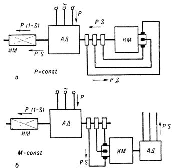
Rice. 1. Schematic diagrams of cascade installations: a — constant power (P = const), b — constant torque (M = const).
To create a cascade installation of an induction motor with a DC machine, it is necessary to include a slip-to-DC energy converter between the rotor of the induction motor and the armature of the DC machine.
The cascade also changes depending on the type of converter. In principle, any modification of the cascade can be carried out both according to the scheme P = const and according to the scheme M = const.
In a single-armature converter cascade (Fig. 2), the speed regulation according to the converter operating conditions is limited to the range of 5 to 45%.
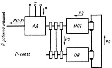
Rice. 2. Schematic diagram of an induction motor cascade and DC machine with a single-armature converter (P = const).
The direction of energy flows in fig. 1, a and b and in fig. 2 is shown for the case of regulating the speed of an induction motor in the subsynchronous zone when the auxiliary collector machine is operating in motor mode. The sliding energy is transmitted to the shaft or to the web.
The operation of an adjustable asynchronous motor with a speed higher than the synchronous one is possible only with a double power supply: on the side of the stator and on the side of the rotor (Fig. 1, b). In this case, the converter works in generator mode.
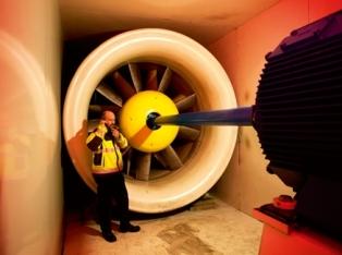
Wind tunnel fans are among the most powerful mechanisms requiring electric drives with a wide range of speed control. Some wind tunnels require electric fan drives of 20,000, 40,000 kW with speed regulation in the range of 1:8 to 1:10 and maintaining the set speed with an accuracy of fractions of %.One of the solutions to this problem was the use of cascade connection of electrical machines.
The large power of the controlled device and the wide range of variation of the rotor frequency of the induction motor made it impossible to use a single-armature converter or to use a generator-motor system, since a direct current machine cannot be filled with power in a single armature by -higher than 7000 kW. In such installations, a two-machine unit consisting of a synchronous motor and a DC generator is used as a converter (Fig. 3).
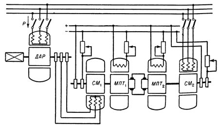
A cascade diagram of an induction motor and a DC machine with a motor-generator converter
The cascade consists of a main variable speed induction motor with a wound rotor, a variable speed unit, a constant speed unit. Speed regulation is done by changing the excitation.