Mechanical characteristics of an induction motor at different modes, voltages and frequencies
 The mechanical characteristics of induction motors can be expressed as n = f (M) or n=e(I). However, the mechanical characteristics of asynchronous motors are often expressed in the form of a dependence M = f(S), where C — sliding, S = (nc-n) / nc, where ns — synchronous speed.
In practice, a simplified formula called the Kloss formula is used for the graphical construction of the mechanical characteristics:

here: Mk — critical (maximum) torque value. This moment value corresponds to the critical slip
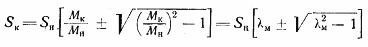
where λm = Mk / Mn
Kloss's formula is used to solve problems related to electric drive performed using an induction motor. Using the Kloss formula, you can build a graph of mechanical characteristics according to the passport data of the induction motor. For practical calculations, only the plus sign should be considered in the formula when determining the critical moment before the root.
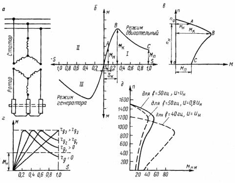
Rice. 1.Asynchronous motor: a — schematic diagram, b — mechanical characteristic M = f (S) — natural in motor and generator modes, c — natural mechanical characteristic n = f (M) in motor mode, d — mechanical characteristics of an artificial rheostat , e — mechanical characteristics for different voltages and frequencies.
Squirrel cage induction motor
As can be seen from fig. 1, mechanical characteristics of an induction motor located in the I and III quadrants. The part of the curve in the I quadrant corresponds to a positive slip value and characterizes the operation mode of the asynchronous motor, and in the III quadrant, the generator mode. The engine mode is of greatest practical interest.
The graph of the mechanical characteristics of the motor mode contains three characteristic points: A, B, C and can be conditionally divided into two sections: OB and BC (Fig. 1, c).
Point A corresponds to the nominal torque of the motor and is determined by the formula Mn = 9.55•103•(Strn /nn)
This moment corresponds nominal slip, which for engines with general industrial application has a value in the range from 1 to 7%, i.e. Sn = 1 — 7%. At the same time, small engines have more slip and large ones have less.
High slip motors intended for shock loading have Сn~15%. These include, for example, single series AC motors.
Point C of the characteristic corresponds to the initial torque value occurring on the motor shaft at start-up. This moment Mp is called initial or starting. In this case, the slip is equal to unity and the velocity is zero. Starting torque it is easy to determine from the data of the reference table, which shows the ratio of the starting torque to the nominal Mp / Mn.
The magnitude of the starting torque at constant values of voltage and current frequency depends on the active resistance in the rotor circuit. In this case, initially as the active resistance increases, the value of the starting torque increases, reaching its maximum when the active resistance of the rotor circuit is equal to the total inductive resistance of the motor. Subsequently, as the active resistance of the rotor increases, the value of the initial torque decreases, tending to zero in the limit.
Point C (Fig. 1, b and c) corresponds to a maximum moment that can develop the engine in the entire range of revolutions from n = 0 to n = ns... This moment is called the critical (or overturning) moment Mk. Critical moment also corresponds to critical slip Sk. The smaller the value of the critical slip Sk, as well as the value of the nominal slip Сn, the greater the stiffness of the mechanical characteristics.
The starting and critical moments are determined by the nominal ones. According to GOST for squirrel-cage motor electric machines, the condition Mn / Mn = 0.9 — 1.2, Mk / Mn = 1.65 — 2.5 must be met.
It should be noted that the value of the critical moment does not depend on the active resistance of the rotor circuit, while the critical slip Сk is directly proportional to this resistance.This means that with an increase in the active resistance of the rotor circuit, the value of the critical moment remains unchanged, but the maximum of the torque curve shifts to increasing slip values (Fig. 1, d).
The magnitude of the critical torque is directly proportional to the square of the voltage applied to the stator and inversely proportional to the square of the frequency of the voltages and the frequency of the current in the stator.
If, for example, the voltage supplied to the motor is equal to 85% of the rated value, then the magnitude of the critical torque will be 0.852 = 0.7225 = 72.25% critical torque at rated voltage.
The opposite is observed when changing the frequency. If, for example, to a motor designed to operate with a current frequency of = 60 Hz, a supply current with a frequency of = 50 Hz, then the critical moment will come in at (60/50)2=1.44 times greater than the official value its frequency (Fig. 1, e).
The critical moment characterizes the instantaneous overload capacity of the motor, that is, it shows what moment (in a few seconds) of overload the motor is able to withstand without any harmful consequences.
The section of the mechanical characteristic from zero to the maximum (critical) value (see Fig. 1, biv) is called the stable part of the characteristic, and the section BC (Fig. 1, c) — the unstable part.
This division is explained by the fact that on the increasing part of the OF characteristics with increasing slip, i.e. as the speed decreases, the torque developed by the engine increases.This means that as the load increases, that is, as the braking torque increases, the rotational speed of the motor decreases, and the torque increased by it increases. When the load decreases, on the contrary, the speed increases and the torque decreases. As the load changes throughout the range of the stable part of the characteristic, the rotational speed and torque of the motor change.
The motor cannot develop more than the critical torque, and if the braking torque is greater, the motor must inevitably stop. An engine rollover happens, as they say.
A mechanical characteristic at constant U and I and the absence of additional resistance in the rotor circuit is called a natural characteristic (characteristic of a squirrel-cage induction motor with a wound rotor without additional resistance in the rotor circuit). Artificial or rheostatic characteristics are called those that correspond to the additional resistance in the rotor circuit.
All starting torque values are different and depend on the active resistance of the rotor circuit. Sliders of different magnitudes correspond to the same nominal torque Mn. As the resistance of the rotor circuit increases, the slip increases and therefore the speed of the motor decreases.
Due to the inclusion of active resistance in the rotor circuit, the mechanical characteristic in the stable part is stretched in the direction of increasing slip, proportional to the resistance.This means that the motor speed starts to vary significantly depending on the shaft load and the hard characteristic becomes soft.