DC valve converters
 Valve DC converters are used to power the field and armature windings of DC electric motors in case a wide range of speed regulation and high quality of the transient modes of the electric drive are required.
For these users, the power circuits of valve converters can be: zero or bridge, single-phase or three-phase. The choice of one or another converter circuit should be based on:
-
providing permissible excitation in the rectified voltage curve,
-
limiting the number and magnitude of higher harmonics Alternating voltage,
-
high use of power transformer.
It is well known that the pulsating rectified converter voltage creates a pulsating current in the motor which disturbs the normal commutation of the motor. In addition, voltage ripples cause additional losses in the motor, which leads to the need to overestimate its power.
Improvement of commutation and reduction of losses in the electric motor can be achieved either by increasing the number of phases of the rectifier, or by introducing a smoothing inductance, or by improving the design of the motor.
If the converter is designed to supply the armature circuit of the motor with low inductance, its most rational power circuits are three-phase: double three-phase zero with a surge reactor, bridge (Fig. 1).
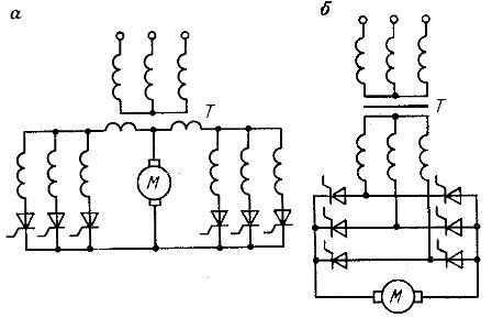
Rice. 1. Supply circuits of three-phase thyristor converters: a — double three-phase zero with equalizing reactor, b — bridge
For powering field coils DC motorswith significant inductance, the power circuits of valve converters can be both three-phase zero and bridge single-phase or three-phase (Fig. 2).
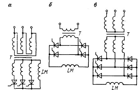
Rice. 2. Schemes of thyristor rectifiers for powering the field windings: a-three-phase zero, b-single-phase bridge, c-three-phase semi-controlled pavement
Of the three-phase rectifier circuits, the most widespread is the three-phase bridge (Fig. 1, b). The advantages of this rectification scheme are: high use of matching three-phase transformer, the smallest value of the reverse voltage of the valves.
For high-power electric drives, the reduction of the rectified voltage ripple is achieved by connecting rectifier bridges in parallel or in series. In this case, the rectifier bridges are powered either by one three-winding transformer or by two two-winding transformers.
In the first case, the primary winding of the transformer is connected "star", and the secondary - in the "star", the other - in the "delta".In the second case, one of the transformers is connected according to the "star-star" scheme, and the second - according to the "delta-star" scheme.
Due to the fact that the primary or secondary windings of the transformers have different connection schemes, the rectified voltage on one bridge will have waveforms that are out of phase at an angle to the rectified voltage waveforms on the other bridge. As a result, the total rectified voltage of the armature of the motor will have ripples, the frequency of which is 2 times higher than the frequency of the waves of each bridge. The equation of the instantaneous values of the rectified voltages in parallel with the connected bridges is carried out by a smoothing reactor. When rectifier bridges are connected in series, the circuit works in a similar way.
To reduce the number of controllable valves, semi-regulated or single bridge circuits are used for correction. In this case, half of the bridge, for example, the cathode group, is controlled, and the anode half is uncontrolled, i.e. assembled on diodes (see Fig. 2, c).
All of the above converter power circuits are irreversible, as they ensure the flow of current in the load in only one direction. The transition from an irreversible to a reversible circuit can be done either by using a contact reverser or by installing two sets of rectifiers. Such rectifiers are made in anti-parallel (Fig. 3) or crossed (Fig. 4) schemes.
In an anti-parallel circuit, both bridges U1 and U2 (see Fig. 3) are fed from the common winding of the transformer and are connected opposite and parallel to each other. In a crossover circuit, each bridge is powered by a separate coil and crossover connected to the load.
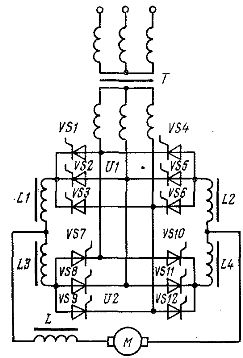
Rice.3. Scheme of anti-parallel connection converters
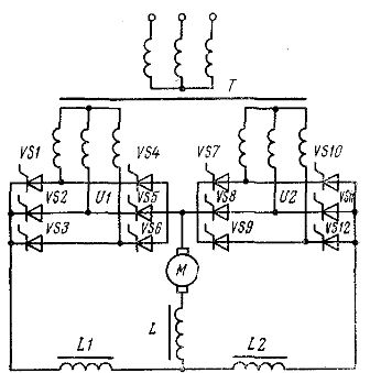
Rice. 4. Diagram of cross-connection of converters
The control of the bridge valves of two-component reversible converters can be separate or joint. In separate control, the control pulses are supplied to the valves of only the bridge that is currently operating and provides the desired direction of current in the load circuit. At the same time, the valves on the other bridge are locked.
In joint control, the control pulses are supplied to the valves of both bridges simultaneously, regardless of the direction of the current in the load. Therefore, with this control, one of the bridges works in rectifier and the other is prepared for inverter mode. Co-governance, on the other hand, can be consistent and inconsistent.
In coordinated control, control pulses are supplied to the valves of both bridges, so that the average values of the corrected voltage y the latter were equal. In the case of inconsistent control, it is necessary that the average rectified voltage of the bridge operating in inverter mode (inverter valve group) exceeds the voltage of the bridge operating in rectifier mode (rectifier valve group).
The operation of reversible circuits with joint control is characterized by the presence of an equalizing current in a closed loop formed by the group valves and the windings of the transformer, which appears due to the inequality of the instantaneous values of the group voltages all the time. To limit the latter, equalizing chokes L1 — L4 are introduced into the circuits (see Fig. 3).
The advantages of joint coordinated control are simplicity, readiness to switch from one mode to another, unambiguous static characteristics, absence of intermittent current mode even at low loads. However, with this control, large equalizing currents flow in the circuit.
Chains with unmatched control have smaller choke sizes than with matched control. However, with such control, the range of allowable control angles decreases, which leads to underutilization of the transformer and a decrease in power factor.
The above disadvantages are deprived of the converter circuit with a separate control. This control method completely eliminates equalizing currents, since in this case the supply of control pulses is carried out only for a working group of valves. Therefore, there is no need to equalize chokes and in general transformer power, since the rectifier group can be opened with the zero value of the adjustment angle.