Electric drive of pump units with frequency
 The operating modes of centrifugal pumps are the most energy efficient to adjust by changing the rotation speed of their wheels. The speed of rotation of the wheels can be changed if an adjustable electric drive is used as the drive motor.
The design and characteristics of gas turbines and internal combustion engines are such that they can provide a change in rotational speed within the required range.
The process of adjusting the rotation speed of each mechanism is conveniently analyzed using the mechanical characteristics of the device.
Consider the mechanical characteristics of a pumping unit consisting of a pump and an electric motor. In fig. 1 shows the mechanical characteristics of a centrifugal pump equipped with a check valve (curve 1) and an electric motor with a squirrel-cage rotor (curve 2).
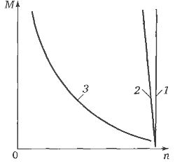
Rice. 1. Mechanical characteristics of the pumping unit
The difference between the torque values of the electric motor and the resistance torque of the pump is called the dynamic torque.If the torque of the motor is greater than the moment of resistance of the pump, the dynamic torque is considered positive, if it is less, it is negative.
Under the influence of a positive dynamic moment, the pump unit begins to work with acceleration, i.e. accelerates. If the dynamic torque is negative, the pump unit operates with a delay, i.e. slows down.
When these moments are equal, a stationary mode of operation takes place, i.e. the pump unit operates at a constant speed. This speed and the corresponding torque are determined by the intersection of the mechanical characteristics of the electric motor and the pump (point a in Fig. 1).
If in the process of adjustment in one way or another the mechanical characteristic changes, for example, to become softer by introducing an additional resistor in the rotor circuit of the electric motor (curve 3 in Fig. 1), the torque of the electric motor will become small of the moment of resistance.
Under the influence of a negative dynamic torque, the pump unit begins to work with a delay, i.e. slows down until the torque and resistance moment balance again (point b in Fig. 1). This point corresponds to the eigenvalue of speed and torque.
Thus, the process of controlling the speed of rotation of the pumping unit is constantly accompanied by changes in the torque of the electric motor and the moment of resistance of the pump.
Control of the pump speed can be done either by changing the speed of the electric motor, which is rigidly connected to the pump, or by changing the gear ratio of the transmission connecting the pump to the electric motor, which runs at a constant speed.
Regulation of the speed of rotation of electric motors
AC motors are mainly used in pumping units. The rotational speed of an AC motor depends on the frequency of the supply current f, the number of pole pairs p and the slip s. By changing one or more of these parameters, you can change the speed of the electric motor and the pump connected to it.
The main element of the frequency electric drive is frequency converter… The inverter has a constant grid frequency f1 converted to variable e2. Proportional to the frequency e2 changes the speed of the electric motor connected to the output of the converter.
With a frequency converter, the mains voltage U1 and the frequency practically do not change f1 converted into variable parameters U2 and e2 necessary for the control system. In order to ensure stable operation of the electric motor, to limit its overload in terms of current and magnetic flux, to maintain high energy indicators in the frequency converter, a certain ratio between its input and output parameters must be maintained depending on the type of mechanical pump characteristics. These relationships are derived from the frequency control law equation.
For pumps, the ratio must be observed:
U1 / f1 = U2 / f2 = const
In fig. 2 shows the mechanical characteristics of an induction motor with frequency regulation.As the frequency f2 decreases, the mechanical characteristic not only changes its position in the n — M coordinates, but to some extent changes its shape. In particular, the maximum torque of the electric motor is reduced. This is due to the fact that with a ratio of U1 / f1 = U2 / f2 = const and the change in frequency f1 does not take into account the effect of the active resistance of the stator on the magnitude of the motor torque.

Rice. 2. Mechanical characteristics of a frequency electric drive at maximum (1) and reduced (2) frequencies
When adjusting the frequency, taking into account this influence, the maximum torque remains unchanged, the shape of the mechanical characteristic is preserved, only its position changes.
Frequency converters with pulse width modulation (PWM) have high energy characteristics due to the fact that the shape of the current and voltage curves approaching the sinusoidal is provided at the output of the converter. Recently, frequency converters based on IGBT modules (insulated gate bipolar transistors) are the most widespread.
The IGBT module is a high-efficiency key element. It features low voltage drop, high speed and low switching power. The frequency converter based on IGBT modules with PWM and vector algorithm for controlling an asynchronous motor has advantages over other types of converters. It has a high power factor over the entire output frequency range.
The schematic diagram of the converter is shown in fig. 3.
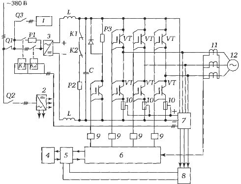
Rice. 3.Scheme of a frequency converter of IGBT modules: 1 — block of fans; 2 — power supply; 3 — uncontrolled rectifier; 4 — control panel; 5 — control panel board; 6 — PWM; 7 — voltage conversion unit; 8 — system control board; 9 — drivers; 10 — fuses for the inverter unit; 11 — current sensors; 12 — asynchronous squirrel-cage motor; Q1, Q2, Q3 — switches for power circuit, control circuit and fan unit; K1, K2 — contactors for charging capacitors and power circuit; C — capacitor bank; Rl, R2, R3 — resistors for limiting the current of the capacitor charge, the discharge of the capacitors and the drain block; VT - Inverter Power Switches (IGBT Modules)
At the output of the frequency converter, a voltage (current) curve is formed, slightly different from a sinusoid, containing higher harmonic components. Their presence leads to an increase in losses in the electric motor. For this reason, when the electric drive operates at a speed close to the rated speed, the electric motor is overloaded.
When operating at reduced speeds, the cooling conditions for self-ventilated electric motors used in pump drives deteriorate. In the normal control range of the pumping units (1: 2 or 1: 3), this deterioration of the ventilation conditions is compensated by a significant reduction in the load due to a reduction in the flow rate and pump head.
When operating at frequencies close to the nominal value (50 Hz), the deterioration of the cooling conditions in combination with the appearance of harmonics of a higher order requires a reduction of the permissible mechanical power by 8-15%.Due to this, the maximum torque of the electric motor is reduced by 1 — 2%, its efficiency — by 1 — 4%, cosφ — by 5-7%.
In order to avoid overloading the electric motor, it is necessary either to limit the upper value of its speed or to equip the drive with a more powerful electric motor. The last measure is mandatory when the pumping unit is designed to operate at a frequency e2> 50 Hz. Limiting the upper value of the engine revolutions is done by limiting the frequency e2 to 48 Hz. The increase in the rated power of the drive motor is rounded up to the nearest standard value.
Group control of variable electric block drives
Many pump sets consist of several blocks. As a rule, not all units are equipped with an adjustable electric drive. From two or three installed units, it is enough to equip one with an adjustable electric drive. If a converter is permanently connected to one of the units, there is an uneven consumption of their motor resource, since the unit equipped with a variable speed drive is used for a much longer time.
For uniform distribution of the load among all the blocks installed at the station, group control stations have been developed, with the help of which the blocks can be connected in series to the converter. Control stations are usually manufactured for low voltage units (380 V).
Typically, low voltage control stations are designed to control two or three units.Low-voltage control stations include circuit breakers that provide protection against phase-phase short circuit and grounding, thermal relays to protect devices from overload, as well as control equipment (switches, button posts and others.).
The switching circuit of the control station contains the necessary interlocks that allow the frequency converter to be connected to any selected block and to replace the working blocks without disturbing the technological mode of operation of the pumping or blowing unit.
Control stations, as a rule, together with power elements (automatic switches, contactors, etc.) contain control and regulating devices (microprocessor controllers, etc.).
At the customer's request, the stations are equipped with devices for automatic switching on of backup power (ATS), commercial measurement of consumed electricity, control of shutdown equipment.
If necessary, additional devices are introduced into the control station, which ensure the use, together with the frequency converter, of the soft starter of the units.
Automated control stations provide:
-
maintaining the set value of the technological parameter (pressure, level, temperature, etc.);
-
control of the operating modes of electric motors of regulated and non-regulated units (control of consumed current, power) and their protection;
-
automatic start of the backup device in case of failure of the main device;
-
switching blocks directly to the network in case of failure of the frequency converter;
-
automatic switching on of the backup (ATS) electrical input;
-
automatic reconnection (AR) of the station after loss and deep voltage drops in the power supply network;
-
automatic change of the operation mode of the station with stopping and starting of the working units at a given time;
-
automatic activation of an additional unregulated unit if the controlled unit, reaching the nominal speed, did not provide the necessary water supply;
-
automatic alternation of work blocks at certain intervals to ensure uniform consumption of motor resources;
-
operational control of the operation mode of the pumping (blowing) unit from the control panel or from the control panel.
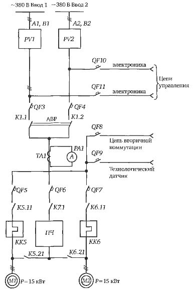
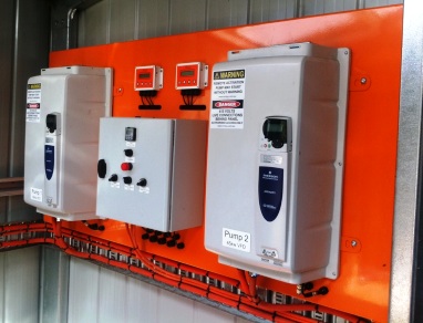
Rice. 4. Station for group control of electric drives of variable frequency pumps
The efficiency of using variable frequency in pumping units
The use of a variable frequency drive allows you to significantly save energy, as it makes it possible to use large pumping units at low flow rates. Thanks to this, it is possible, by increasing the unit capacity of the units, to reduce their total number and, accordingly, to reduce the overall dimensions of the buildings, to simplify the hydraulic scheme of the station and to reduce the number of pipeline valves.
Thus, the use of adjustable electric drive in pumping units allows, along with saving electricity and water, to reduce the number of pumping units, to simplify the hydraulic circuit of the station and to reduce the construction volumes of the building of the pumping station.In this connection, secondary economic effects arise: the costs of heating, lighting and repair of the building are reduced, the reduced costs, depending on the purpose of the stations and other specific conditions, can be reduced by 20-50%.
Technical documentation for frequency converters shows that the use of an adjustable electric drive in pumping units allows you to save up to 50% of the energy spent on pumping clean and waste water, and the payback period is from three to nine months.
At the same time, calculations and analysis of the effectiveness of controlled electric drive in operating pump units show that for small pump units with units with a power of up to 75 kW, especially when they work with a large static pressure component, it turns out not suitable to use controlled electric drives. In these cases, you can use simpler control systems by using throttling, changing the number of working pump units.
The use of variable electric drive in pump unit automation systems, on the one hand, reduces energy consumption, and on the other hand, requires additional capital costs, therefore the possibility of using variable electric drive in pump units is determined by comparing the reduced costs of two options: basic and new. A pumping unit equipped with an adjustable electric drive is taken as a new option, and a unit whose units operate at a constant speed is taken as the main one.