Electric drives for CNC machines
 Modern multifunctional metal-cutting machines and industrial robots are equipped with multi-motor electric drives that move executive bodies along several coordinate axes (Fig. 1).
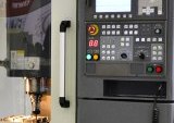
Control of the operation of a CNC machine is carried out using standard systems that generate commands in accordance with a program defined in digital form. The creation of high-performance microcontrollers and single-chip microcomputers, which make up the programmable CPU core, made it possible with their help to automatically perform many geometric and technological operations, as well as to perform direct digital control of the electric drive system and electro-automation.
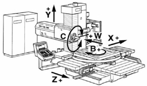
Rice. 1. Drive system of CNC milling machine
Types of electric drives for CNC machines and requirements for them
The process of cutting metal is carried out by mutual movement of the part to be processed and the blade of the cutting tool.Electric drives are part of metal cutting machines, which are designed to perform and regulate metalworking processes through a CNC system.
In processing, it is customary to separate the main movements that provide controlled cutting processes during the mutual movement of the tool and the workpiece, as well as auxiliary movements that facilitate the automatic operation of the equipment (approaching and withdrawing monitoring tools, changing tools and etc.).
The main ones include the main cutting movement, which has the highest speed and power, which provides] the necessary cutting force, as well as the feed movement, which is necessary to move the working body along a spatial trajectory at a given speed. To obtain the surface of the product with a given shape, the working bodies of the machine tell the workpiece and the tool to move the desired trajectory with a set speed and force. Electric drives give rotational and translational movements to the working bodies, the combinations of which, through the kinematic structure of the machines, provide the necessary mutual displacements.
The purpose and type of metalworking machine largely depends on the shape of the manufactured part (body, shaft, disc). The ability of a multifunction machine to generate the tool and workpiece movements required during machining is determined by the number of coordinate axes and therefore by the number of interconnected electric drives and the structure of the control system.
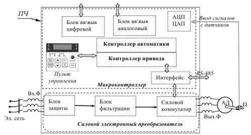
Currently, drives are mainly performed on the basis of reliable AC motors with frequency controlcarried out by digital regulators.Different types of electric drives are implemented using typical industrial modules (Fig. 2).
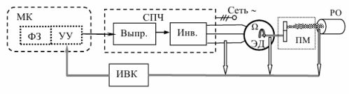
Rice. 2. Typical functional diagram of an electric drive
The minimum composition of the electric drive blocks consists of the following functional blocks:
-
executive electric motor (ED);
-
frequency power converter (HRC), which converts the electrical power of the industrial network into a three-phase motor supply voltage of the required amplitude and frequency;
-
a microcontroller (MC) that performs the functions of a control unit (CU) and a task generator (FZ).
The industrial unit of the power frequency converter contains a rectifier and a power converter that generate a sinusoidal voltage with the necessary parameters determined by the signals of the control device using microprocessor control of the output PWM switch.
The algorithm for controlling the operation of the electric drive is implemented by the microcontroller by generating commands obtained as a result of comparing the signals of the task generator and the data received from the information-computing complex (IVC) based on the processing and analysis of signals from a set from sensors.
The electric prime mover drive in most applications contains an induction electric motor with a squirrel-cage rotor winding and a gearbox as the mechanical transmission of rotation to the machine spindle. The gearbox is often designed as a gearbox with electromechanical remote gear shifting.The electric drive of the main movement provides the necessary cutting force at a certain rotational speed, and therefore the purpose of speed regulation is to maintain constant power.
The necessary range of rotation speed control depends on the diameters of the processed products, their materials and many other factors. In modern automated CNC machines, the main drive performs complex functions related to thread cutting, machining of parts of different diameters, and much more. This leads to the need to provide a very large range of speed control as well as the use of a reversible drive. In multifunction machines, the required rotation speed range can be thousands or more.
Very large speed ranges are also required in feeders. So, in contour milling you should theoretically have an infinite speed range, as the minimum value tends to zero at some points. Often, the rapid movement of the working bodies in the processing area is also carried out by a feeder, which greatly increases the range of speed change and complicates the drive control systems.
In feeders, synchronous motors and non-contact DC motors are used, as well as in some cases asynchronous motors. The following basic requirements apply to them:
-
wide range of speed regulation;
-
high top speed;
-
high overload capacity;
-
high performance during acceleration and deceleration in positioning mode;
-
high positioning accuracy.
The stability of the drive characteristics must be guaranteed under load variations, changes in ambient temperature, supply voltage and many other reasons. This is facilitated by the development of a rational adaptive automatic control system.
Mechanical part of the drive of the machine
The mechanical part of the drive can be a complex kinematic structure containing many parts rotating at different speeds. The following elements are usually distinguished:
-
rotor of an electric motor that creates torque (rotating or braking);
-
mechanical transmission, t, s. a system that determines the nature of movement (rotational, translational) and changes the speed of movement (reducer);
-
a working body that converts the energy of movement into useful work.
Asynchronous drive tracking of the main motion of the metal cutting machine
The modern adjustable electrical drive of the main movement of CNC metalworking machines is mainly based on asynchronous motors with a cage rotor winding, which has been facilitated by many factors, among which it should be noted the improvement of the elementary information base and power electronics.
The regulation of the modes of alternating current motors is carried out by changing the frequency of the supply voltage using a power converter, which, along with frequency regulation, changes other parameters.
The characteristics of the tracking electric drive largely depend on the efficiency of the built-in ACS.The use of high-performance microcontrollers has provided wide opportunities for organizing electric drive control systems.
Rice. 3. Typical control structure of the induction motor using a frequency converter
The drive controller generates sequences of numbers for the power switch that regulates the operation of the electric motor. The automation controller provides the necessary characteristics in the start and stop modes, as well as automatic adjustment and protection of the equipment.
The hardware part of the computing system also contains: - analog-digital and digital-analog converters for entering signals from sensors and controlling their operation;
-
input and output modules for analog and digital signals, equipped with interface equipment and cable connectors;
-
interface blocks that perform internal intermodule data transmission and communication with external equipment.
A large number of settings of the frequency converter, introduced by the developer, taking into account the detailed data of a particular electric motor, provide certain control procedures, among which it can be noted:
-
multi-level speed regulation,
-
upper and lower frequency limit,
-
torque limit,
-
braking by supplying direct current to one of the motor phases,
-
overload protection, but in case of overload and overheating, providing power saving mode.
Drive based on contactless DC motors
Machine tool drives have high requirements for the range of speed control, linearity of control characteristics and speed, as they determine the accuracy of the relative positioning of the tool and the part, as well as the speed of their movement.
Power drives were implemented mainly on the basis of DC motors, which had the necessary control characteristics, but at the same time, the presence of a mechanical brush collector was associated with low reliability, complexity of maintenance and a high level of electromagnetic interference.
The development of power electronics and digital computing technologies contributed to their replacement in electric drives with contactless direct current motors, which made it possible to improve the energy characteristics and increase the reliability of machine tools. However, contactless motors are relatively expensive due to the complexity of the control system.
But the principle of operation of a brushless motor is a direct current electric machine with a magnetoelectric inductor on the rotor and armature windings on the stator. The number of stator windings and the number of poles of the rotor magnets are selected depending on the required characteristics of the motor. Increasing them helps improve ride and handling, but leads to a more complex engine design.
When driving metal-cutting machines, a structure with three armature windings, made in the form of several connected sections, and an excitation system of permanent magnets with several pairs of poles are mainly used (Fig. 4).
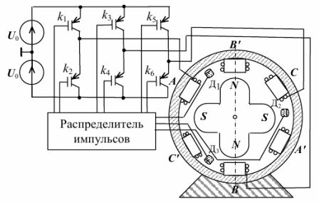
Rice. 4. Functional diagram of a contactless DC motor
The torque is formed due to the interaction of the magnetic fluxes created by the currents in the stator windings and the permanent magnets of the rotor. The constant direction of the electromagnetic moment is ensured by suitable commutation supplied to the stator windings with direct current. The sequence of connection of the stator windings to the source U is carried out by means of power semiconductor switches, which are switched under the action of signals from the pulse distributor when supplying voltage from the rotor position sensors.
In the task of regulating the operating modes of the electric drive of non-contact DC motors, the following interrelated issues are distinguished:
-
development of algorithms, methods and means of controlling an electromechanical converter by affecting physical quantities available for measurement;
-
creating an automatic drive control system using the theory and methods of automatic control.
Electro-hydraulic drive based on a stepper motor
In modern machine tools, joint electro-hydraulic drives (EGD) are semi-common, in which discrete electrical signals coming from an electronic CNC system are converted by synchronous electric motors into shaft rotation. The torque developed under the action of the signals of the drive controller (CP) of the CNC system from the electric motor (EM) is the input value for the hydraulic amplifier connected through the mechanical transmission (MP) to the executive body (IO) of the machine tool (Fig. 5).
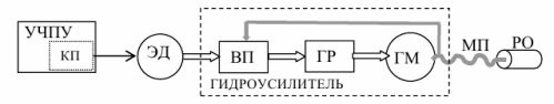
Rice. 5. Functional scheme of the electro-hydraulic drive
The controlled rotation of the electric motor rotor by means of the input transformation (VP) and the hydraulic valve (GR) causes the rotation of the hydraulic motor shaft (GM). In order to stabilize the parameters of the hydraulic amplifier, internal feedback is usually used.
In the electric drives of mechanisms with a start-stop nature of movement or continuous movement, stepper motors (SM) have found application, which are classified as a type of synchronous electric motors. Pulse-excited stepper motors are best suited for direct digital control used in CNC control.
Intermittent (stepwise) movement of the rotor at a certain angle of rotation for each pulse makes it possible to obtain sufficiently high positioning accuracy with a very large range of speed variation from almost zero.
When you use a stepper motor in an electric drive, it is controlled by a device containing a logic controller and a switch (Fig. 6).
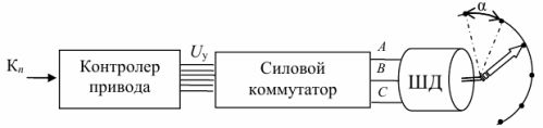
Rice. 6. Stepper motor control device
Under the action of the nchannel selection control command, the CNC drive controller generates digital signals to control the power transistor switch, which in the required sequence connects the DC voltage to the stator windings. To obtain small values of angular displacement in one step α = π / p, a permanent magnet with a large number of pole pairs p is placed on the rotor.