The principle of operation and the device of the electric motor
Any electric motor is designed to perform mechanical work due to the consumption of electricity applied to it, which is usually converted into rotary motion. Although in technology there are models that immediately create a translational movement of the working body. These are called linear motors.
In industrial installations, electric motors drive various metal-cutting machines and mechanical devices involved in the technological production process.
Inside household appliances, electric motors run washing machines, vacuum cleaners, computers, hair dryers, children's toys, clocks, and many other devices.
Basic physical processes and principle of action
When moving inside magnetic field electric charges, which are called electric currents, always have a mechanical force that tends to deflect their direction in a plane perpendicular to the orientation of the magnetic field lines.When an electric current passes through a metal wire or a coil made of it, this force tends to move/rotate each current-carrying wire and the entire coil as a whole.
The photo below shows a metal frame with current flowing through it. A magnetic field applied to it creates a force F for each branch of the frame, which creates a rotational motion.

This property of the interaction of electric and magnetic energy, based on the creation of an electromotive force in a closed conducting loop, is put into operation on every electric motor. Its design includes:
-
a coil through which an electric current flows. It is placed on a special anchor core and fixed in rotary bearings to reduce resistance to frictional forces. This design is called a rotor;
-
stator, which creates a magnetic field, which with its lines of force penetrates electric charges passing along the turns of the rotor winding;
-
housing for placing stator. Inside the body, special seats are made, inside which the outer cages of the rotor bearings are mounted.
The simplified design of the simplest electric motor can be represented by a picture of the following form.

When the rotor rotates, a torque is generated, the power of which depends on the general design of the device, the amount of applied electrical energy and its losses during conversions.
The magnitude of the maximum possible torque power of the motor is always less than the electrical energy applied to it. It is characterized by the efficiency value.
Types of electric motors
According to the type of current flowing through the coils, they are divided into DC or AC motors.Each of these two groups has a large number of modifications using different technological processes.
DC motors
They have a stator magnetic field created by a stationary fixed permanent magnets or special electromagnets with excitation coils. The armature coil is firmly mounted in the shaft, which is fixed in bearings and can rotate freely around its own axis.
The basic structure of such an engine is shown in the figure.

On the core of the armature, made of ferromagnetic materials, there is a coil consisting of two series-connected parts, which are connected to the conducting collector plates at one end and connected to each other at the other. Two graphite brushes are located at diametrically opposite ends of the armature and are pressed against the contact pads of the collector plates.
A positive DC source potential is applied to the lower pattern brush and a negative potential to the upper one. The direction of the current flowing through the coil is shown by a dashed red arrow.
The current causes the magnetic field to have a north pole at the lower left of the armature, and a south pole at the upper right of the armature (gimbal rule). This results in repulsion of the rotor poles from the stationary ones of the same name and attraction to the opposite poles of the stator. As a result of the applied force, a rotational movement occurs, the direction of which is indicated by a brown arrow.
With further rotation of the armature by inertia, the poles are transferred to other collector plates. The direction of the current in them is reversed. The rotor continues to rotate further.
The simple design of such a collector device leads to large losses of electrical energy.Such motors work in devices of simple design or toys for children.
The direct current electric motors involved in the production process have a more complex design:
-
the coil is divided not into two, but into several parts;
-
each section of the coil is mounted on its own pole;
-
the collector device is made with a certain number of contact pads according to the number of windings.
As a result, a smooth connection of each pole through its contact plates to the brushes and the current source is created and energy losses are reduced.
The device of such an anchor is shown in the photo.
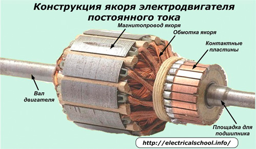
In DC motors, the direction of rotation of the rotor can be reversed. To do this, it is enough to change the movement of the current in the coil to the opposite by changing the polarity at the source.
AC motors
They differ from previous designs in that the electric current flowing in their coil is described by sinusoidal harmonic lawperiodically changing its direction (sign). To power them, voltage is supplied from generators with alternating signs.
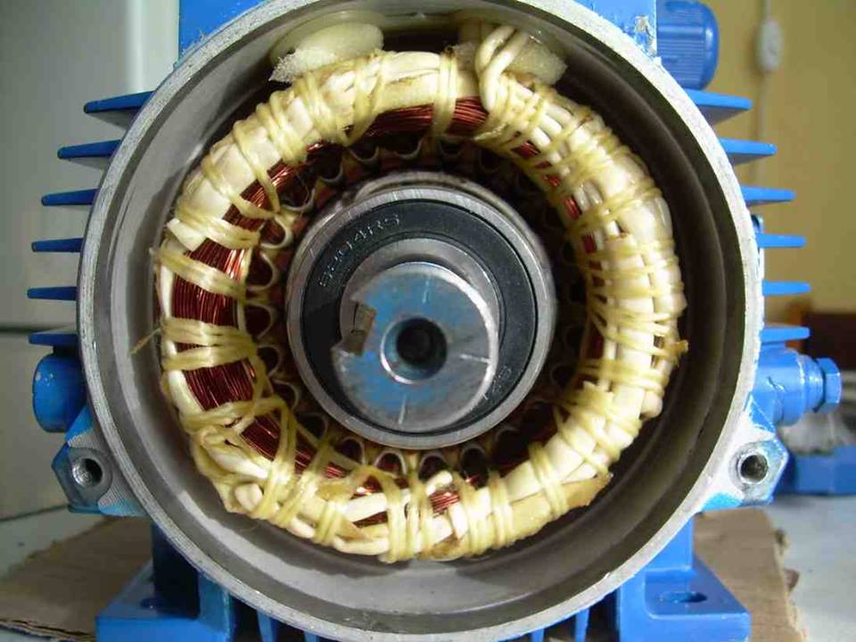
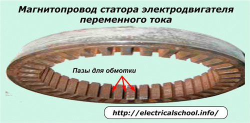
The stator of such motors is performed by a magnetic circuit. It is made of ferromagnetic plates with grooves in which the turns of the coil are placed with a frame (coil) configuration.
Synchronous electric motors
The photo below shows the principle of operation of a single-phase AC motor with synchronous rotation of the electromagnetic fields of the rotor and stator.

In the grooves of the magnetic circuit of the stator at diametrically opposite ends, winding wires are placed, schematically shown in the form of a frame through which an alternating current flows.
Let us consider the case of the moment in time corresponding to the passage of the positive part of its half-wave.
In the bearing cells, a rotor with a built-in permanent magnet rotates freely, in which the northern «N mouth» and the southern «S mouth» of the pole are clearly defined. When a positive half-wave of current flows through the stator winding, a magnetic field with poles «S st» and «N st» is created in it.
Interaction forces arise between the magnetic fields of the rotor and the stator (with the poles repelling and unlike the poles attracting) which tend to turn the motor armature from any position to the extreme when the opposite poles are located as close as possible to each other another.
If we consider the same case, but for the moment in time when the opposite - a negative half-wave of current passes through the frame wire, then the rotation of the armature will occur in the opposite direction.
To ensure continuous movement of the rotor in the stator, not one winding frame is made, but a certain number of them, given that each of them is powered by a separate current source.
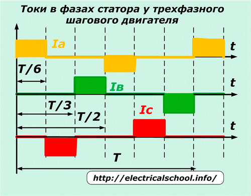
Working principle of a three-phase AC motor with synchronous rotation, the electromagnetic fields of the rotor and stator are shown in the following picture.

In this design, three coils A, B and C are mounted inside the stator magnetic circuit, offset by angles of 120 degrees to each other. Coil A is marked yellow, B is green, and C is red. Each coil is made with the same frames as in the previous case.
In the picture, in any case, the current flows through only one coil in the forward or reverse direction, which is indicated by the signs «+» and «-«.
When the positive half-wave passes through phase A in the forward direction, the axis of the rotor field takes a horizontal position, because the magnetic poles of the stator are formed in this plane and attract the movable armature. The opposite poles of the rotor tend to approach the poles of the stator.
When the positive half wave goes into phase C, the armature will rotate 60 degrees clockwise. Once current is applied to phase B, a similar armature rotation will occur. Each subsequent current flow in the next phase of the next winding will turn the rotor.
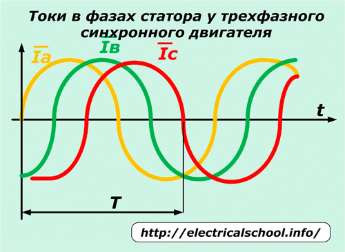
If a three-phase mains voltage shifted by an angle of 120 degrees is applied to each winding, then alternating currents will circulate in them, which will rotate the armature and create its synchronous rotation with the supplied electromagnetic field.
The same mechanical design is used successfully in a three-phase stepper motor… Only in each winding by control special controller (stepper motor driver) Constant pulses are applied and removed according to the algorithm described above.
Their start-up starts a rotational movement, and their termination at a certain point in time provides a measured rotation of the shaft and a stop at a programmed angle to perform certain technological operations.
In both three-phase systems described, it is possible to change the direction of rotation of the armature. To do this, you just need to change the sequence of phases «A» — «B» — «C» to another, for example «A» — «C» — «B».
The speed of the rotor is regulated by the length of the period T. Its reduction leads to an acceleration of the rotation.The magnitude of the amplitude of the current in the phase depends on the internal resistance of the winding and the value of the voltage applied to it. It determines the amount of torque and power of the electric motor.
Asynchronous motors
These motor designs have the same stator magnetic circuit with windings as in the previously discussed single-phase and three-phase models. They get their name from the asynchronous rotation of the armature and stator electromagnetic fields. This is done by improving the configuration of the rotor.
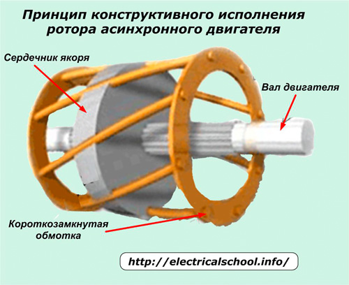
Its core is made of grooved electrical steel plates. They are equipped with aluminum or copper current conductors, which are closed at the ends of the armature with conductive rings.
When voltage is applied to the stator windings, an electric current is induced in the rotor winding by electromotive force and an armature magnetic field is created. When these electromagnetic fields interact, the motor shaft begins to rotate.
With this design, the movement of the rotor is possible only after the occurrence of a rotating electromagnetic field in the stator, and it continues in an asynchronous mode of operation with it.
Asynchronous motors are simpler in design. Therefore, they are cheaper and are widely used in industrial installations and household appliances.
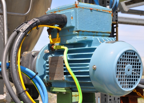
ABB explosion-proof electric motor
Linear motors
Many working bodies of industrial mechanisms perform reciprocating or translational movement in one plane, which is necessary for the operation of metalworking machines, vehicles, hammer blows when driving piles ...
Moving such a working body by means of gearboxes, ball screws, belt drives and similar mechanical devices from a rotary electric motor complicates the design. The modern technical solution to this problem is the operation of a linear electric motor.
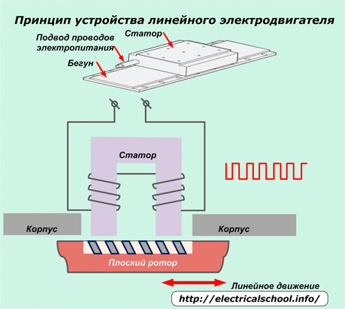
Its stator and rotor are elongated in the form of strips, rather than wound into rings, as in rotary electric motors.
The principle of operation is to impart reciprocating linear motion to the runner rotor due to the transfer of electromagnetic energy from a stationary stator with an open magnetic circuit of a certain length. A working magnetic field is created inside it by sequentially switching on the current.
It acts on the armature winding with a collector. The forces arising in such a motor move the rotor only in a linear direction along the guide elements.
Linear motors are designed to operate on either direct current or alternating current and can operate in synchronous or asynchronous mode.
The disadvantages of linear motors are:
-
the complexity of the technology;
-
high price;
-
low energy efficiency.