Electromagnetic compatibility when using frequency converters
 Electromagnetic Compatibility (EMC) This is the ability of electrical or electronic equipment to function normally in the presence of electromagnetic fields. At the same time, the equipment must not interfere with the operation of other equipment or systems nearby.
The International Energy Commission (IEC) EMC Directive sets immunity and emission requirements for electrical equipment used in the European Economic Area. The EMC EN 61800-3 standard covers the requirements for frequency converters.
The frequency converter draws current from the source only during periods when the instantaneous value of the sine wave of the power source is higher than the DC link voltage, i.e. in the peak source voltage region. As a result, the current does not flow continuously, but intermittently, with very high peak values.
This type of current waveform includes, along with the fundamental frequency components, a more or less high proportion of harmonic components (supply harmonics).
In three-phase frequency converters, they mainly consist of 5th, 7th, 11th and 13th harmonics. These currents cause distortion of the supply voltage waveform, which affects other electrical consumers in the same network.
In addition, alternating currents cause fluctuations in power factor correction circuits under some critical conditions that may lead to overvoltage.
Conditions are critical when:
-
at least 10 — 20% of the power of the installation is formed by the inverter and the uncontrolled rectifier of the frequency converter;
-
the compensation circuit works without interruption;
-
the lowest compensation stage creates a resonant circuit together with the supply transformer and a resonant frequency close to 5 or 7 harmonics of 50 Hz, i.e. around 250 or 350 Hz.
As a result of the very fast switching of the inverter transistors at pulse width modulation acoustic effects are observed, which have a negative impact on the power grid and the electric motor.
The rapid switching of the transistor switches of the inverter results in a broadband interference signal that affects the environment through the motor cables. The continuous changes in inductance caused by PWM and DTC control voltage intervals result in slight changes in the length of the motor core sheets (magnetostriction), resulting in a characteristic modulated noise in the motor stator core stack.
The output voltage of the frequency converter is high frequency rectangular pulse train with different polarity and duration with the same amplitude.The steepness of the front of the voltage pulse is determined by the switching speed of the power switches of the inverter and is different when using different semiconductor devices (for example: for IGBT transistors this is 0.05 — 0.1 μs).
The passage of a pulse signal with a steep front causes wave processes in the cable and leads to overvoltages in the motor terminals.
The length of the motor cable depends on the length of the high-frequency wave (pulse front) propagating through it. Critical is a cable length equal to half the wavelength at which voltage pulses are applied to the windings of the induction motor, which are close in magnitude to twice the DC link voltage.
In electric drives for voltage class 0.4 kV, the overvoltage can reach 1000 V. This problem is called long cable problems.
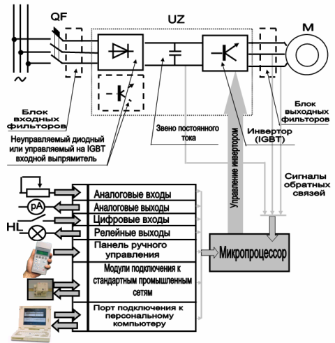
Block diagram of a frequency converter with input and output filters
To meet the requirements of EMC standards, line chokes and EMC filters are used in frequency converter drives.
EMC filters reduce the acoustic noise emitted by the transducer and for most types of transducers are factory built into the probe housing. Line reactors are designed to reduce high inrush currents and therefore harmonics of the line current and to improve the surge protection of the regulated frequency drive.
The solution to the «long cable» problem is the need to apply technical solutions to limit overvoltages and inrush currents in the terminals of the electric motor. These include installing output chokes, filters, sinusoidal filters.
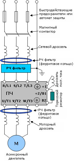
Frequency converter connection diagram
Output chokes primarily serve to limit the current spikes that occur in long motor cables due to overcharging of the cable receptacles and slightly reduce the voltage rise at the motor terminals, but they do not reduce the voltage peaks at the motor terminals.

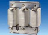
Linear choke
The filters protect the motor insulation by limiting the voltage rise and reducing the voltage peaks at the motor terminals to non-critical values, while the filters reduce the current peaks that occur when the cable containers are periodically recharged.
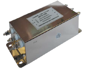
EMC filters
Sinusoidal filters provide a near-sinusoidal voltage at the output of the converter.
In addition, sinusoidal filters reduce the rate of rise of the motor terminal voltage to a value, remove voltage peaks, reduce additional losses in the motor and reduce motor noise.
For long motor cables, sinusoidal filters reduce the current peaks generated by periodic recharging of the cable containers.
In addition to the above methods of limiting surge voltages in the terminals of the electric motor, two effective ways to solve the problem of a long cable should be noted, which do not require large investments and can be carried out directly by the user:
1. Installation of a series LC — filter at the output of the frequency converter to reduce the steepness of the leading edge of the inverter output voltage pulses;
2.Installing a parallel RC filter directly to the motor terminals to match the wave impedance of the cable.
In addition to the above methods of ensuring electromagnetic compatibility, it should be noted the need to use shielded cables to connect the frequency converter and the electric motor. For effective suppression of radiated high-frequency interference, the conductivity of the screen should be at least 1/10 of the conductivity of the phase conductor.
One of the parameters that allow to evaluate the conductivity of the screen is its inductance, which should be small and depend as little as possible on the frequency. These requirements are easily met using a copper or aluminum shield (armor).
The shields of the cable connecting the frequency converter and the motor must be grounded at both ends. The better and tighter the shield, the lower the radiation level and the magnitude of the current in the motor bearings.
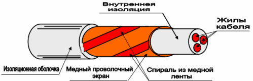
Screen of the motor cable for the frequency converter
The shield consists of a concentric layer of copper wires and a coiled copper strip.
Normally the shield of the control cable is grounded directly to the frequency converter. The other end of the shield is left ungrounded or connected to ground via a high voltage high frequency capacitor of a few nF.
It is recommended to use a twisted pair cable with two shields to connect analog signals. The use of such a cable is also recommended for connecting signals from an impulse speed sensor. One cable with a separate shield should be used for each signal.
For low-voltage digital signals, it is also recommended to use a double-shielded twisted-pair cable, but multiple twisted-pair cables with a common shield can be used.
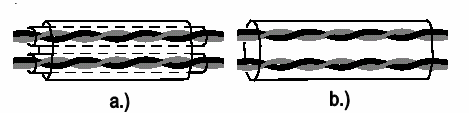
Double-shielded twisted-pair cable (a) and cable with several twisted pairs and one common shield (b)