Frequency converter - types, principle of operation, connection schemes
 The rotor of any electric motor is driven by forces caused by a rotating electromagnetic field inside the stator winding. Its speed is usually determined by the industrial frequency of the power grid.
Its standard value of 50 hertz implies fifty oscillation periods in one second. In one minute, their number increases 60 times and is 50×60 = 3000 revolutions. The rotor rotates the same number of times under the influence of the applied electromagnetic field.
If you change the value of the mains frequency applied to the stator, you can adjust the speed of rotation of the rotor and the drive connected to it. This principle is the basis of the control of electric motors.
Types of frequency converters
By design, frequency converters are:
1. induction type;
2. electronic.
Manufactured asynchronous motors according to the scheme with a phase rotor and started in generator mode, are representatives of the first type. During operation, they have low efficiency and are characterized by low efficiency.Therefore, they have not found wide application in production and are used extremely rarely.
The electronic frequency conversion method allows smooth speed regulation of both asynchronous and synchronous machines. In this case, one of two control principles can be applied:
1. According to a predetermined characteristic of the dependence of the rotation speed on the frequency (V / f);
2. vector control method.
The first method is the simplest and less perfect, and the second is used to precisely control the rotational speeds of critical industrial equipment.
Features of frequency conversion vector control
The difference between this method is the interaction, the influence of the converter control device on the «space vector» of the magnetic flux rotating with the frequency of the rotor field.
Algorithms for converters to work on this principle are created in two ways:
1. sensorless control;
2. flow regulation.
The first method is based on determining a certain dependence on the alternation of sequences pulse width modulation (PWM) inverter for preset algorithms. In this case, the amplitude and frequency of the converter output voltage are controlled by slip current and load, but without using rotor speed feedback.
This method is used when controlling several electric motors connected in parallel with the frequency converter.Flux control involves monitoring the operating currents inside the motor with their decomposition into active and reactive components and making adjustments to the converter operation to set the amplitude, frequency and angle for the output voltage vectors.
This improves the accuracy of the engine and increases the limits of its regulation. The use of flow control extends the capabilities of drives operating at low speeds with high dynamic loads, such as crane hoists or industrial winding machines.
The use of vector technology allows dynamic torque control to be implemented three-phase asynchronous motors.
Equivalent circuit
A basic simplified electrical circuit of an induction motor can be represented as follows.
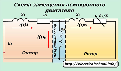
A voltage u1 is applied to the stator windings, which have an active resistance R1 and an inductive resistance X1. It, overcoming the resistance of the air gap Xv, is transformed into the rotor winding, causing in it a current that overcomes its resistance.
Equivalent circuit of a vector circuit
Its construction helps to understand the processes taking place in the induction motor.
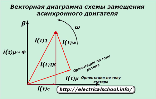
The energy of the stator current is divided into two parts:
-
iµ — flow-forming partition;
-
iw — moment generating component.
In this case, the rotor has a slip-dependent active resistance R2 / s.
For sensorless control, the following is measured:
-
voltage u1;
-
current i1.
According to their values, they calculate:
-
iµ — flow component forming the flow;
-
iw — value generating torque.
The calculation algorithm now includes an electronic equivalent circuit of an induction motor with current regulators, which takes into account the saturation conditions of the electromagnetic field and the losses of magnetic energy in steel.
Both components of the current vectors, different in angle and amplitude, rotate together with the rotor coordinate system and become a stationary stator orientation system.
According to this principle, the parameters of the frequency converter are adjusted according to the load of the induction motor.
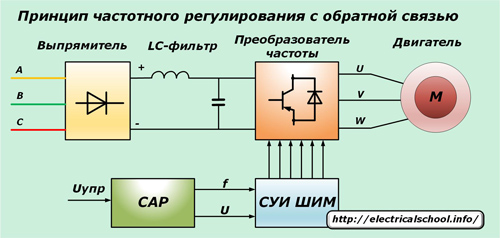
The principle of operation of the frequency converter
This device, which is also called an inverter, is based on a double change in the waveform of the mains power supply.
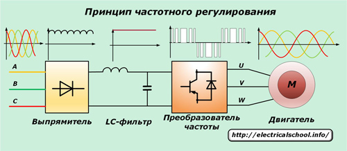
Initially, industrial voltage is fed to a rectifier with powerful diodes that remove sinusoidal harmonics but leave the signal ripples. For their removal, a capacitor bank with an inductance (LC-filter) is provided, which provides a stable, smoothed shape to the rectified voltage.
The signal then goes to the input of the frequency converter, which is a three-phase bridge circuit of six power transistors IGBT or MOSFET series with reverse polarity voltage protection diodes. Previously used thyristors for these purposes do not have sufficient speed and operate with large disturbances.
To turn on the "brake" mode of the motor, a controlled transistor with a powerful resistor that dissipates energy can be installed in the circuit. This technique allows the voltage generated by the motor to be removed to protect the filter capacitors from overcharging and damage.
The vector frequency control method of the converter allows you to create circuits that perform automatic control of the signal from ACS systems. A management system is used for this:
1. amplitude;
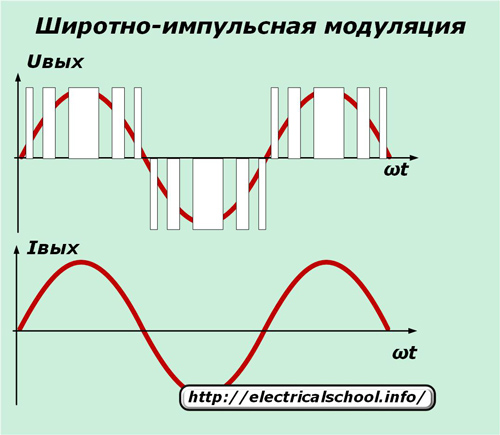
2. PWM (pulse width simulation).
The amplitude control method is based on changing the input voltage, and PWM is based on the algorithm for switching the power transistors at a constant input voltage.
With PWM regulation, a period of signal modulation is created when the stator winding is connected in strict order to the positive and negative terminals of the rectifier.
Since the clock frequency of the generator is quite high, then in the winding of the electric motor, which has inductive resistance, they are smoothed to a normal sine wave.
PWM control methods maximize the elimination of energy losses and provide high conversion efficiency due to the simultaneous control of frequency and amplitude. They have become available due to the development of GTO series power-locked thyristor control technologies or bipolar brands of insulated-gate IGBT transistors.
The principles of their inclusion for controlling a three-phase motor are shown in the photo.
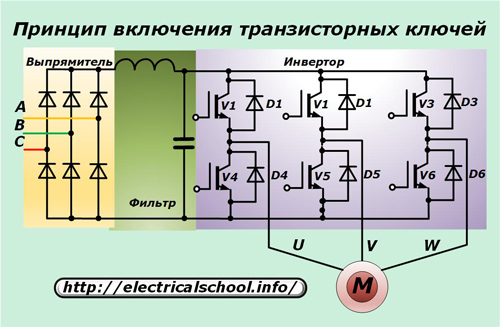
Each of the six IGBTs is connected in antiparallel circuit to its own reverse current diode. In this case, the active current of the induction motor passes through the power circuit of each transistor, and its reactive component is directed through the diodes.
In order to eliminate the influence of external electrical noise on the operation of the inverter and the motor, the circuit of the frequency converter can include noise reduction filterliquidation:
-
radio interference;
-
electrical discharges caused by operating equipment.
These are signaled by the controller and shielded wiring is used between the motor and the inverter output terminals to reduce shock.
To improve the accuracy of operation of asynchronous motors, the control circuit of frequency converters includes:
-
communication input with advanced interface capabilities;
-
built-in controller;
-
memory card;
-
software;
-
informational LED display showing the main output parameters;
-
brake chopper and built-in EMC filter;
-
circuit cooling system based on blowing with fans of increased resource;
-
the function of heating the engine by direct current and some other possibilities.
Operational wiring diagrams
Frequency converters are designed to work with single-phase or three-phase networks. However, if there are industrial sources of direct current with a voltage of 220 volts, then inverters can be powered from them.
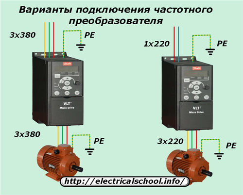
Three-phase models are designed for mains voltage 380 volts and feed it to the electric motor. Single-phase inverters are powered by 220 volts and output three phases distributed over time.
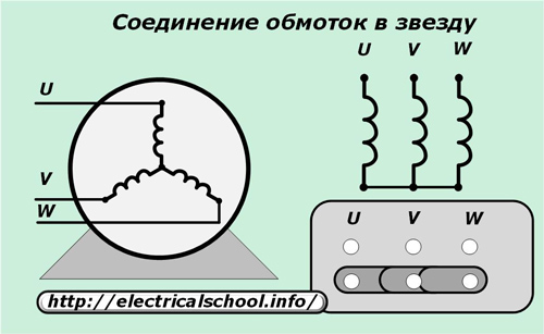
The connection scheme of the frequency converter to the motor can be carried out according to the schemes:
-
stars;
-
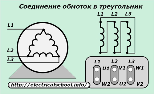
triangle.
The windings of the motor are assembled in a «star» for the converter, fed by a three-phase network of 380 volts.
According to the "delta" scheme, the motor windings are assembled when the power converter is connected to a single-phase 220-volt network.
When choosing a method of connecting an electric motor to a frequency converter, you need to pay attention to the power ratio that a running motor can create in all modes, including a slow, loaded start, with the capabilities of the inverter.
It is impossible to constantly overload the frequency converter, and a small reserve of its output power will ensure its long-term and trouble-free operation.