Reactance in electrical engineering
Famous in electrical engineering Ohm's Law explains that if a potential difference is applied to the ends of a section of the circuit, then an electric current will flow under its action, the strength of which depends on the resistance of the medium.
AC voltage sources create a current in the circuit connected to them, which may follow the shape of the source's sine wave or be shifted forward or backward by an angle from it.

If the electric circuit does not change the direction of the current flow and its phase vector completely coincides with the applied voltage, then such a section has a purely active resistance. When there is a difference in the rotation of the vectors, they speak of the reactive nature of the resistance.
Different electrical elements have different ability to deflect the current flowing through them and change its magnitude.
Reactance of the coil
Take a stabilized AC voltage source and a piece of long insulated wire. First, we connect the generator to the entire straight wire, and then to it, but wound in rings around magnetic circuit, which is used to improve the passage of magnetic fluxes.
By accurately measuring the current in both cases, it can be seen that in the second experiment, a significant decrease in its value and a phase lag at a certain angle will be observed.
This is due to the appearance of opposite forces of induction manifested under the action of Lenz's law.
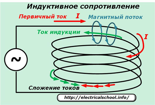
In the figure, the passage of the primary current is shown by red arrows, and the magnetic field generated by it is shown in blue. The direction of its movement is determined by the right-hand rule. It also crosses all adjacent turns inside the coil and induces a current in them, shown by the green arrows, which weakens the value of the applied primary current while shifting its direction relative to the applied EMF.
The more turns wound on the coil, the more inductive reactance X.Lreduces the primary current.
Its value depends on the frequency f, the inductance L, calculated by the formula:
xL= 2πfL = ωL
By overcoming inductance forces, the coil current lags the voltage by 90 degrees.
Transformer resistance
This device has two or more coils on a common magnetic circuit. One of them receives electricity from an external source, and it is transmitted to the others according to the principle of transformation.
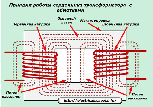
The primary current passing through the power coil induces a magnetic flux in and around the magnetic circuit, which crosses the turns of the secondary coil and forms a secondary current in it.
Because it is perfect for creating transformer design is impossible, then some of the magnetic flux will dissipate into the environment and create losses.These are called leakage flux and affect the amount of leakage reactance.
To these is added the active component of the resistance of each coil. The total value obtained is called the electrical impedance of the transformer or its complex resistance Z, creating a voltage drop across all windings.
For the mathematical expression of the connections inside the transformer, the active resistance of the windings (usually made of copper) is indicated by the indices "R1" and "R2", and the inductive by "X1" and "X2".
The impedance in each coil is:
-
Z1 = R1 + jX1;
-
Z2 = R1 + jX2.
In this expression, the subscript «j» denotes an imaginary unit located on the vertical axis of the complex plane.
The most critical regime in terms of inductive resistance and the occurrence of a reactive power component is created when the transformers are connected in parallel operation.
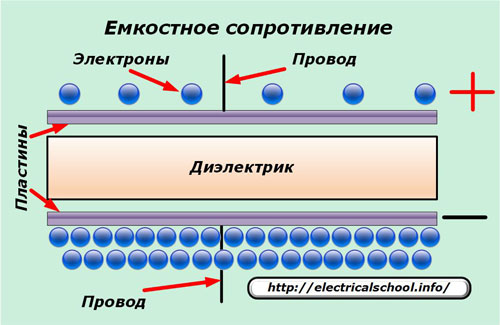
Capacitor resistance
Structurally, it includes two or more conductive plates separated by a layer of material with dielectric properties. Because of this separation, direct current cannot pass through the capacitor, but alternating current can, but with a deviation from its original value.
Its change is explained by the principle of action of reactive - capacitive resistance.
Under the action of an applied alternating voltage, changing in a sinusoidal form, a jump occurs on the plates, an accumulation of charges of electrical energy with opposite signs. Their total number is limited by the size of the device and is characterized by capacity. The bigger it is, the longer it takes to charge.
During the next half-cycle of oscillation, the polarity of the voltage across the capacitor plates is reversed.Under its influence, there is a change in the potentials, a recharge of the formed charges on the plates. In this way, the flow of the primary current is created and the opposition to its passage is created as it decreases in magnitude and moves along the angle.
Electricians have a joke about this. Direct current on the graph is represented by a straight line, and when it passes along the wire, the electric charge, reaching the capacitor plate, rests on the dielectric, getting into a dead end. This obstacle prevents him from passing.
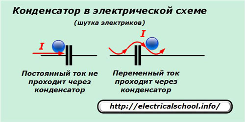
The sinusoidal harmonic passes through obstacles and the charge, rolling freely on the painted plates, loses a small fraction of the energy that is captured on the plates.
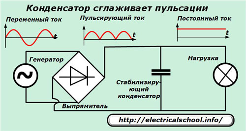
This joke has a hidden meaning: when a constant or rectified pulsating voltage is applied to the plates between the plates, due to the accumulation of electric charges from them, a strictly constant potential difference is created, which smooths out all jumps in the power supply circuit. This property of a capacitor with increased capacitance is used in constant voltage stabilizers.
In general, the capacitive resistance Xc, or the opposition to the passage of alternating current through it, depends on the design of the capacitor, which determines the capacitance «C», and is expressed by the formula:
Xc = 1/2πfC = 1 / ω° C
Due to the recharging of the plates, the current through the capacitor raises the voltage by 90 degrees.
Reactivity of the power line
Every power line is designed to transmit electrical energy. It is customary to represent it as equivalent circuit sections with distributed parameters of active r, reactive (inductive) x resistance and conductance g, per unit length, usually one kilometer.
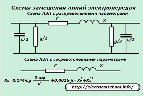
If we neglect the influence of capacitance and conductance, then we can use a simplified equivalent circuit for a line with parallel parameters.
Overhead power line
Transmission of electricity over exposed bare wires requires a significant distance between them and from the ground.
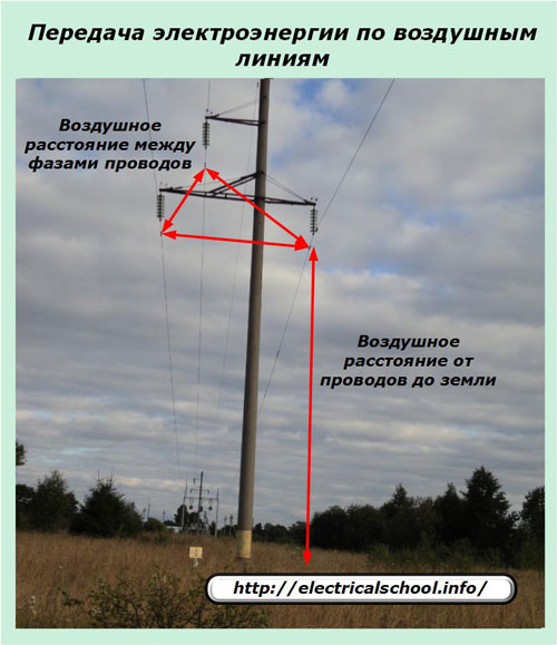
In this case, the inductive resistance of one kilometer of three-phase conductor can be represented by the expression X0. Depends:
-
average distance of the axes of the wires between each other asr;
-
outer diameter of phase wires d;
-
relative magnetic permeability of the material µ;
-
external inductive resistance of the line X0 ';
-
internal inductive resistance of the line X0 «.
For reference: the inductive resistance of 1 km of an overhead line made of non-ferrous metals is about 0.33 ÷ 0.42 Ohm / km.
Cable transmission line
A power line using a high voltage cable is structurally different from an overhead line. Its distance between the phases of the wires is significantly reduced and is determined by the thickness of the internal insulation layer.
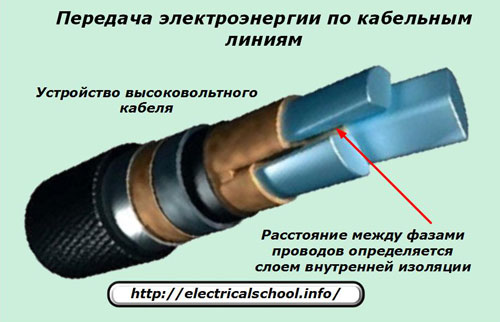
Such a three-wire cable can be represented as a capacitor with three sheaths of wires stretched over a long distance. As its length increases, the capacitance increases, the capacitive resistance decreases, and the capacitive current that closes along the cable increases.
Single-phase ground faults most often occur in cable lines under the influence of capacitive currents. For their compensation in 6 ÷ 35 kV networks, arc suppression reactors (DGR) are used, which are connected through the grounded neutral of the network. Their parameters are selected by sophisticated methods of theoretical calculations.
Old GDRs did not always work effectively due to poor tuning quality and design imperfections. They are designed for the average rated fault currents, which often differ from the actual values.
Nowadays, new developments of GDRs are introduced, capable of automatically monitoring emergency situations, quickly measuring their main parameters and adjusting for reliable extinguishment of earth fault currents with an accuracy of 2%. Thanks to this, the efficiency of the GDR operation immediately increases by 50%.
The principle of compensation of the reactive component of power from capacitor units
Power grids transmit high-voltage electricity over long distances. Most of its users are electric motors with inductive resistance and resistive elements. The total power sent to consumers consists of the active component P, used to do useful work, and the reactive component Q, which causes heating of the windings of transformers and electric motors.
The reactive component Q arising from inductive reactances reduces power quality. To eliminate its harmful effects in the eighties of the last century, a compensation scheme was used in the power system of the USSR by connecting capacitor banks with capacitive resistance, which reduced cosine of an angle φ.
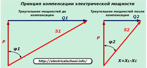
They were installed at substations that directly feed the problem consumers. This ensures local regulation of power quality.
In this way, it is possible to significantly reduce the load on the equipment by reducing the reactive component while transmitting the same active power.This method is considered the most effective method of saving energy not only in industrial enterprises, but also in residential and communal services. Its competent use can significantly improve the reliability of power systems.