How the control mechanisms of fluorescent lamps are arranged and work
The class of gas-discharge light sources, which include fluorescent lamps, requires the use of special equipment that performs the passage of an arc discharge inside a sealed glass housing.
The device and principle of operation of a fluorescent lamp
Its shape is made in the form of a tube. It can be straight, curved or twisted.
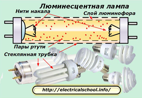
The surface of the glass bulb is covered with a layer of phosphorus from the inside, and tungsten filaments are located at its ends. The inner volume is sealed, filled with low pressure inert gas with mercury vapor.
The glow of a fluorescent lamp occurs due to the creation and maintenance of an electric arc discharge in an inert gas between the filaments, which work on the principle of thermionic radiation. For its flow, an electric current is passed through the tungsten wire to heat the metal.
At the same time, a high potential difference is applied between the filaments, providing energy for the flow of an electric arc between them.Mercury vapor improves the flow path for it in an inert gas environment. The phosphor layer transforms the optical characteristics of the outgoing light beam.
It deals with ensuring the passage of electrical processes inside the fluorescent lamp control equipment... Abbreviated PRA.
Types of ballasts
Depending on the element base used, ballast devices can be made in two ways:
1. electromagnetic design;
2. electronic unit.
The first models of fluorescent lamps worked exclusively by the first method. For this we used:
-
starter;
-
throttle.
Electronic blocks appeared not so long ago. They began to be produced after the massive, rapid development of enterprises producing a modern assortment of electronic bases based on microprocessor technology.
Electromagnetic ballasts
The principle of operation of a fluorescent lamp with an electromagnetic ballast (EMPRA)
The starting circuit of the starter with the connection of an electromagnetic choke is considered traditional, classic. Because of its relative simplicity and low cost, it remains popular and continues to be widely used in lighting schemes.
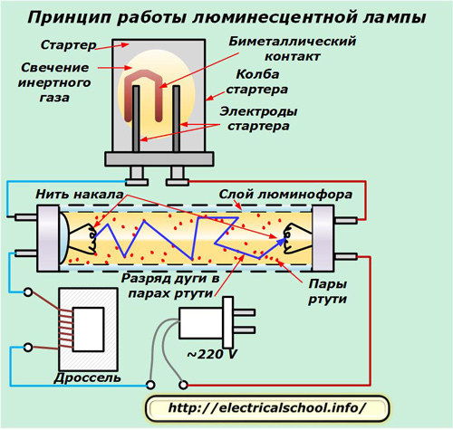
After supplying the mains to the lamp, the voltage is supplied through the choke coil and the tungsten filaments to starter electrodes… It is designed in the form of a gas discharge lamp with a small size.
Mains voltage applied to its electrodes causes a glow discharge between them, forming an inert gas glow and heating its environment. Close by bimetallic contact perceive it, bend. changes shape and closes the gap between the electrodes.
A closed circuit is formed in the circuit of the electrical circuit and a current begins to flow through it, heating the filaments of the fluorescent lamp. A thermionic emission is formed around them. At the same time, the mercury vapor inside the flask is heated.
The resulting electric current reduces the voltage applied from the network to the electrodes of the starter by about half. The lightning between them decreases and the temperature drops. The bimetallic plate reduces its bending by disconnecting the circuit between the electrodes. The current through them is interrupted and an EMF of self-induction is created inside the choke. It immediately creates a short-term discharge in the circuit connected to it: between the filaments of a fluorescent lamp.
Its value reaches several kilovolts. It is enough to create the decay of an inert gas medium with heated mercury vapor and heated filaments to a state of thermionic radiation. An electric arc occurs between the ends of the lamp, which is the source of light.
At the same time, the voltage at the contacts of the starter is not enough to destroy its inert layer and re-close the electrodes of the bimetallic plate. They remain open. The starter does not participate in the further scheme of work.
After starting the glow, the current in the circuit must be limited. Otherwise, the circuit elements may burn. This function is also assigned to throttle… Its inductive resistance limits the rise of the current and prevents damage to the lamp.
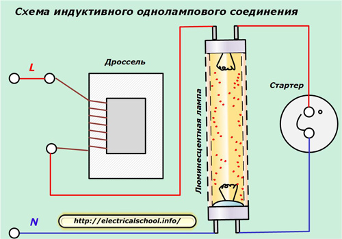
Connection diagrams of electromagnetic ballasts
Based on the above principle of operation of fluorescent lamps, various connection schemes are created for them through a control device.
The simplest is to turn on the choke and the starter for one lamp.
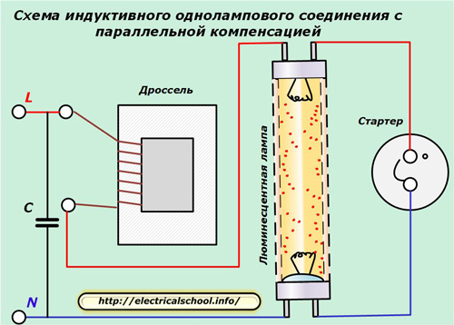
In this method, an additional inductive resistance appears in the supply circuit. To reduce reactive power losses from its action, compensation is used due to the inclusion of a capacitor at the input of the circuit, shifting the angle of the current vector in the opposite direction.
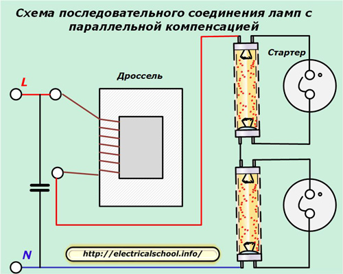
If the power of the choke allows it to be used to operate several fluorescent lamps, the latter are collected in series circuits, and separate starters are used to start each.
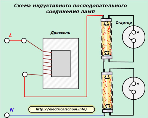
When it is necessary to compensate the effect of inductive resistance, the same technique is used as before: a compensation capacitor is connected.
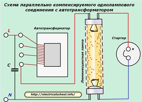
Instead of a choke, an autotransformer can be used in the circuit, which has the same inductive resistance and allows you to adjust the value of the output voltage. The compensation of active power losses of the reactive component is done by connecting a capacitor.
Autotransformer can be used for lighting with several lamps connected in series.
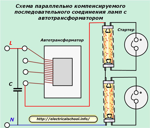
At the same time, it is important to create a reserve of its power to ensure reliable operation.
Disadvantages of using electromagnetic ballasts
The dimensions of the throttle require the creation of a separate housing for the control device, which occupies a certain space. At the same time, it emits, albeit small, external noise.
The starter design is not reliable. Periodically, the lamps go out due to malfunctions. If the starter fails, a false start occurs when several flashes can be visually observed before a steady burn begins. This phenomenon affects the life of threads.
Electromagnetic ballasts create relatively high energy losses and reduce efficiency.
Voltage multipliers in circuits for driving fluorescent lamps
This scheme is often found in amateur designs and is not used in industrial designs, although it does not require a complex base of elements, is easy to manufacture and is efficient.
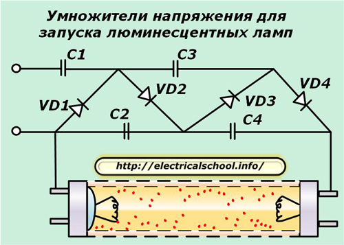
The principle of its operation consists in gradually increasing the supply voltage of the network to significantly greater values, causing the destruction of the insulation of an inert gas medium with mercury vapor without heating it and ensuring thermionic radiation of the threads.
Such a connection allows the use of even bulbs with burnt filaments. To do this, in their circuit, the bulbs are simply shunted with external jumpers on both sides.
Such circuits have an increased risk of electric shock to a person. Its source is the output voltage from the multiplier, which can be brought up to kilovolts and more.
We do not recommend this chart for use and are publishing it to clarify the danger of the risks it poses. We draw your attention to this matter on purpose: do not use this method yourself and warn your colleagues about this major drawback.
Electronic ballasts
Features of the operation of a fluorescent lamp with an electronic ballast (ECG)
All the physical laws that arise inside a glass flask with inert gas and mercury vapor to form an arc discharge and glow remain unchanged in the design of lamps controlled by electronic ballasts.
Therefore, the algorithms for the operation of electronic ballasts remain the same as those of their electromagnetic counterparts. It's just that the old element base has been replaced with a modern one.
This ensures not only the high reliability of the control device, but also its small dimensions, which allows it to be installed in any suitable place, even inside the base of a conventional E27 bulb developed by Edison for incandescent lamps.
According to this principle, small energy-saving lamps with a fluorescent tube of a complex twisted shape, which do not exceed in size incandescent lamps, work and are designed to be connected to the 220 network through old sockets.
In most cases, for electricians who work with fluorescent lamps, it is enough to imagine a simple connection diagram made with great simplification from a few components.
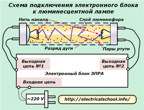
From the electronic block for electronic ballasts to work there are:
-
input circuit connected to a 220 volt power supply;
-
two output circuits #1 and #2 connected to the respective threads.
Usually, the electronic unit is made with a high degree of reliability, a long service life. In practice, energy-saving lamps most often loosen the bulb body during operation for various reasons. The inert gas and mercury vapor leave it immediately. Such a lamp will no longer light up, and its electronic unit remains in good condition.
It can be reused by connecting to a flask of suitable capacity. For this:
-
the base of the lamp is carefully disassembled;
-
the electronic ECG unit is removed from it;
-
mark a pair of wires used in the power circuit;
-
mark the wires of the output circuits on the filament.
After that, it remains only to reconnect the circuit of the electronic unit to a complete, working flask. She will continue to work.
Electromagnetic ballast device
Structurally, the electronic block consists of several parts:
-
a filter that removes and blocks electromagnetic interference coming from the power supply to the circuit or created by the electronic unit during operation;
-
rectifier of sinusoidal oscillations;
-
power correction circuits;
-
smoothing filter;
-
inverter;
-
electronic ballast (an analogue of a choke).
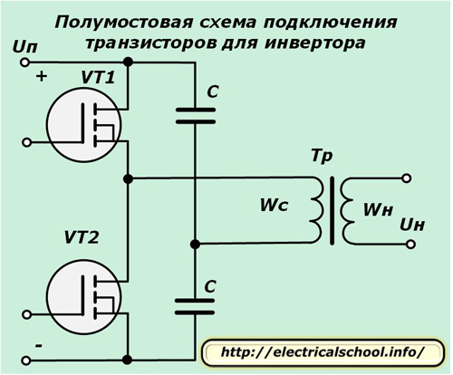
The electric circuit of the inverter works on powerful field effect transistors and is created according to one of the typical principles: a bridge or half-bridge circuit for their inclusion.
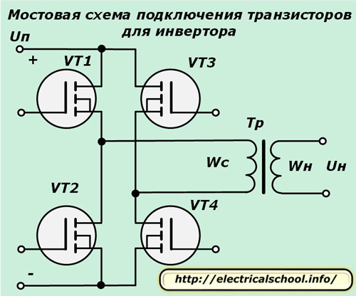
In the first case, four keys operate in each arm of the bridge. Such inverters are designed to convert high power in lighting systems into hundreds of watts. A half-bridge circuit contains only two switches, has lower efficiency, and is used more often.
Both circuits are controlled by a special electronic unit — microdar.
How electronic ballasts work
To ensure reliable luminescence of the fluorescent lamp, the ECG algorithms are divided into 3 technological stages:
1. preparatory, related to the initial heating of the electrodes in order to increase the thermionic radiation;
2. igniting the arc by applying a high-voltage pulse;
3. Ensuring a stable arc discharge.
This technology allows you to quickly turn on the lamp even at negative temperatures, provides a soft start and output of the minimum necessary voltage between the filaments for good arc lighting.
One of the simple schematic diagrams for connecting an electronic ballast to a fluorescent lamp is shown below.
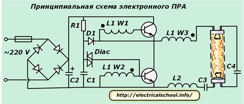
A diode bridge at the input rectifies the AC voltage. Its waves are smoothed by capacitor C2.A push-pull inverter connected in a half-bridge circuit works after it.
It includes 2 n-p-n transistors that create high-frequency oscillations that are fed with control signals in antiphase to the windings W1 and W2 of the three-winding toroidal high-frequency transformer L1. Its remaining coil W3 supplies a high resonant voltage to the fluorescent tube.
Thus, when the power is turned on before lighting the lamp, a maximum current is created in the resonant circuit, which ensures heating of both filaments.
A capacitor is connected in parallel with the lamp. A large resonant voltage is created on its plates. It fires an electric arc in an inert gas environment. Under its action, the capacitor plates are short-circuited and the voltage resonance is interrupted.
However, the lamp does not stop burning. It continues to work automatically due to the remaining share of the applied energy. The inductive resistance of the converter regulates the current passing through the lamp, keeping it in the optimal range.