Frequency regulation of an asynchronous motor
Currently, frequency control of the angular speed of rotation of an electric drive with an asynchronous motor is widely used, since it allows in a wide range to smoothly change the speed of rotation of the rotor both above and below the nominal value.
Frequency converters are modern, high-tech devices with a wide adjustment range that have an extensive set of functions for controlling asynchronous motors. The highest quality and reliability make it possible to use them in various industries to control drives of pumps, fans, conveyors, etc.

Frequency converters for supply voltage are divided into single-phase and three-phase, but by design, into rotating and static electrical machines. In electric machine converters, the variable frequency is obtained by using conventional or special electric machines. V static frequency converters the change in the frequency of the supply current is achieved by the use of electrical elements that have no motion.
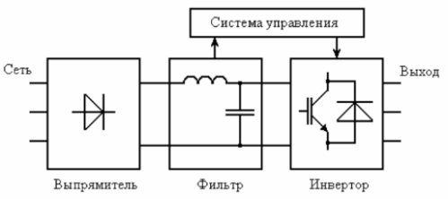
Frequency converter circuit of an induction motor
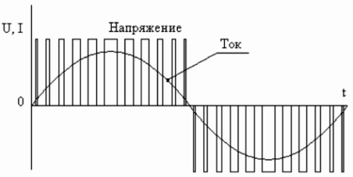
Output signal of the frequency converter
Frequency converters for single-phase mains can provide electric drive for production equipment with a power of up to 7.5 kW. A feature of the design of modern single-phase converters is that at the input there is one phase with a voltage of 220V, and at the output there are three phases with the same voltage value, which allows connecting three-phase electric motors to a device without using capacitors.
Frequency converters powered by 380V three-phase network are available in the power range from 0.75 to 630 kW. Depending on the power value, devices are produced in polymer combined and metal cases.
The most popular control strategy for induction motors is vector control. Currently, most frequency converters implement vector control or even sensorless vector control (this trend is found in frequency converters that originally implement scalar control and do not have terminals for connecting a speed sensor).
Depending on the type of output load, frequency converters are subdivided according to the type of implementation:
-
for pump and fan drives;
-
for general industrial electric propulsion;
-
works as part of electric motors operating with overload.
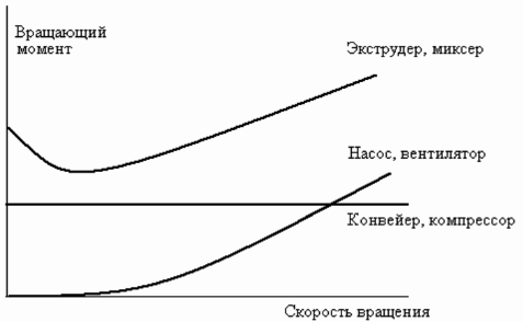
Mechanical characteristics of typical loads
Modern frequency converters have a diverse set of functional characteristics, for example, they have manual and automatic control of the speed and direction of rotation of the motor, as well as built-in potentiometer on the control panel.Gifted with the ability to adjust the output frequency range from 0 to 800 Hz.
Converters are able to automatically control an asynchronous motor according to signals from peripheral sensors and drive an electric drive according to a given timing algorithm. Support automatic recovery functions in case of short-term power failure. Perform transient control from a remote console and protect electric motors from overload.
The relationship between the angular velocity of rotation and the frequency of the supply current follows from Eq
ωo = 2πe1/ p
With a constant supply voltage U1 and a change in frequency, the magnetic flux of the induction motor changes. At the same time, for better use of the magnetic system, with a decrease in the power supply frequency, it is necessary to reduce the voltage proportionally, otherwise the magnetizing current and losses in the steel will increase significantly.
Similarly, as the supply frequency increases, the voltage must increase proportionally to keep the magnetic flux constant, because otherwise (with a constant shaft torque) this will cause the rotor current to increase, overloading of its windings by current and reducing the maximum torque.
The rational voltage regulation law depends on the nature of the resistance moment.
At a constant moment of static load (Ms = const), the voltage must be regulated in proportion to its frequency U1 / f1 = const. For the nature of the fan load, the ratio takes the form U1 / f21 = const.
With load torque inversely proportional to speed U1 /√f1 = const.
The figures below show a simplified connection diagram and mechanical characteristics of an induction motor with frequency control of angular speed.

Connection diagram of a frequency converter to an asynchronous motor
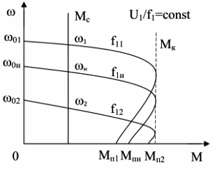
Characteristics for a load with a constant static moment of resistance
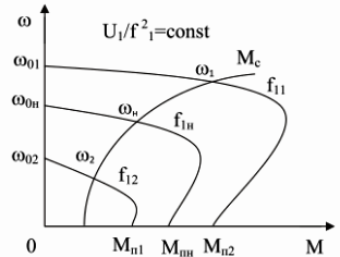
NSFeatures for charging the fan
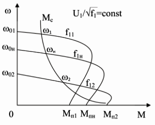
Characteristics under static load torque inversely proportional to the angular velocity of rotation
Frequency regulation of the speed of an asynchronous motor allows you to change the angular speed of rotation in the range — 20 … 30 to 1. Regulation of the speed of an asynchronous motor down from the main one is carried out practically to zero.
When the frequency of the supply network changes, the upper limit of the rotational speed of an asynchronous motor depends on its mechanical properties, especially since at frequencies above the nominal asynchronous motor operates with better energy characteristics than at lower frequencies. Therefore, if a gearbox is used in the drive system, this frequency control of the motor must be carried out not only down, but also up from the nominal point, up to the maximum permissible speed of rotation under the conditions of the mechanical strength of the rotor.
When the engine speed increases above the value indicated in its passport, the frequency of the power source should not exceed the nominal one by no more than 1.5 — 2 times.
The frequency method is most promising for the regulation of a squirrel-cage rotor induction motor. Power losses with such regulation are small, as they are not accompanied by an increase in slipping… The resulting mechanical characteristics are highly rigid.