Pulse width modulation
PWM or PWM (Pulse Width Modulation) is a way of controlling the power supply to a load. The control consists in changing the pulse duration at a constant pulse repetition rate. Pulse Width Modulation is available in analog, digital, binary, and ternary.
The use of pulse-width modulation makes it possible to increase the efficiency of electrical converters, especially for pulse converters, which today form the basis of secondary power supplies for various electronic devices. Flyback and forward single, push-pull and half-bridge, as well as bridge switching converters are controlled today with the participation of PWM, this also applies to resonant converters.
Pulse width modulation allows you to adjust the brightness of the backlight of liquid crystal displays of mobile phones, smartphones, laptops. PWM is implemented in welding machines, in car inverters, in chargers, etc. Every charger today uses PWM in its operation.
Key-mode bipolar and field-effect transistors are used as switching elements in modern high-frequency converters. This means that part of the period the transistor is fully open and part of the period it is fully closed.
And since in transient states lasting only tens of nanoseconds, the power released by the switch is small compared to the switched power, as a result, the average power released in the form of heat on the switch turns out to be negligible. In this case, in the closed state, the resistance of the transistor as a switch is very small, and the voltage drop across it approaches zero.
In the open state, the conductivity of the transistor is close to zero and the current practically does not flow through it. This makes it possible to create compact converters with high efficiency, that is, with low heat losses. ZCS (Zero Current Switching) resonant converters minimize these losses.
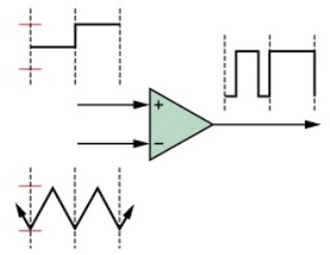
In analog-type PWM generators, the control signal is generated by an analog comparator when, for example, a triangle or triode signal is applied to the inverting input of the comparator and a modulating continuous signal is applied to the non-inverting input.
Output pulses are received rectangular, their repetition rate is equal to the frequency of the saw (or triangular waveform), and the duration of the positive part of the pulse is related to the time during which the level of the modulating DC signal applied to the non-inverting input of the comparator is higher than the level of the saw signal that is fed to the inverting input.When the saw voltage is higher than the modulating signal, the output will be the negative part of the pulse.
If the saw is applied to the non-inverting input of the comparator, and the modulating signal is applied to the inverting one, then the square wave output pulses will have a positive value when the saw voltage is higher than the value of the modulating signal applied to the inverting input, and negative — when the saw voltage is lower than the modulating signal. An example of analog PWM generation is the TL494 chip, which is widely used today in the construction of switching power supplies.
Digital PWM is used in binary digital technology. The output pulses also take only one of two values (on or off), and the average output level approaches the desired one. Here, the sawtooth signal is obtained by using an N-bit counter.
PWM digital devices also operate at a constant frequency, necessarily exceeding the response time of the controlled device, this approach is called oversampling. Between clock edges, the digital PWM output remains stable, high or low, depending on the current state of the output of the digital comparator, which compares the levels of the counter signal and the approximate digital one.
The output is clocked as a sequence of pulses with states 1 and 0, each state of the clock may or may not be reversed. The frequency of the pulses is proportional to the level of the approaching signal, and successive units can form a wider, longer pulse.
The resulting variable-width pulses will be multiples of the clock period, and the frequency will be equal to 1 / 2NT, where T is the clock period, N is the number of clock cycles. A lower frequency in terms of clock frequency is achievable here. The digital generation scheme described is one-bit or two-level PWM, pulse-coded PCM modulation.
This two-stage pulse-coded modulation is essentially a sequence of pulses with a frequency of 1/T and a width of T or 0. Oversampling is used to average over a longer period of time. High-quality PWM is achieved by single-bit pulse-dense modulation, also called pulse-frequency modulation.
In digital pulse-width modulation, the rectangular subpulses that fill the period can appear anywhere in the period, and then only their number affects the average value of the signal for the period. So if we divide the period into 8 parts, then the pulse combinations 11001100, 11110000, 11000101, 10101010, etc. will give the same period average, but the individual units make the duty cycle of the key transistor heavier.
The luminaries of electronics, speaking of PWM, give a similar analogy to mechanics. If you turn a heavy flywheel with the engine after the engine can be turned on or off, the flywheel will either spin and continue to spin or stop due to friction when the engine is off.
But if the engine is turned on for a few seconds per minute, then the rotation of the flywheel will be maintained due to inertia at a certain speed. And the longer the engine is turned on, the higher the speed of rotation of the flywheel.So with PWM, an on and off signal (0 and 1) comes to the output and the result is an average value. By integrating the voltage of the pulses over time, we obtain the area under the pulses, and the effect on the working body will be identical to the work with an average value of the voltage.
This is how converters work, where switching occurs thousands of times per second, and frequencies reach units of megahertz. Special PWM controllers are widely used to control the ballasts of energy-saving lamps, power supplies, frequency converters for motors etc.
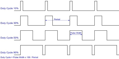
The ratio of the total duration of the pulse period to the on-time (positive part of the pulse) is called the duty cycle. So, if the turn-on time is 10 μs, and the period lasts 100 μs, then at a frequency of 10 kHz, the duty cycle will be 10, and they write that S = 10. The reverse duty cycle is called the duty cycle, in English Duty cycle or DC for short.
So, for the given example, DC = 0.1 since 10/100 = 0.1. With pulse-width modulation, by adjusting the duty cycle of the pulse, that is, by changing the direct current, the required average value is achieved at the output of an electronic or other electrical device, such as a motor.